Reznor MAPS - A,B,C Users Manual User Manual
Page 27
Form O-MAPSIII&IV Cabinets A/B/C, P/N 257004R8, Page 27
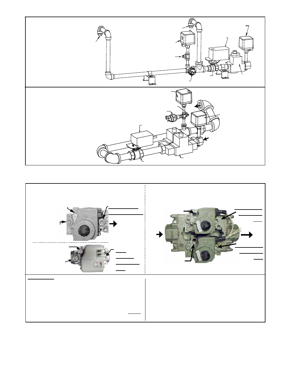
Optional High Gas
Pressure Switch
Optional Low
Gas Pressure
Switch
Dual, Single-Stage Gas Valve
Ball Valve
Transducer
From Gas
Supply
To
Burner
Manifold Pressure Tap
Ball Valve
Actuator
FIGURE 15C -
Components in the
Heat Section Gas
Train - MAPS
®
III&IV
Cabinet C (Heat
Section Sizes 400,
500, 600, 700)
Single-Stage Operating Gas Valve - All gas trains have either a single-stage or a dual single-stage safety gas valve.
The gas valve must be checked annually to ensure that it is shutting off gas flow completely; follow the instructions in
box below.
Instructions:
1. Locate the 1/8" NPT pressure tap or taps on the
combination valve.
2. Turn the knob(s) or switch to the OFF position to
prevent flow to the manifold. Connect a manometer to
each of the 1/8” outlet pressure taps (1 on the single-
stage valve; 2 on the dual single-stage valve).
NOTE:
Manometers (fluid-filled gauges) with inches water
column scale are recommended. Turn the heater off.
On the valve, turn the knob(s) or switch to the ON
position.
3. Use finger(s) to fully block the burner orifice(s).
Continue blocking for several seconds and observe
the manometers. If any pressure is indicated, the gas
valve is leaking. A leaking gas valve must be replaced
before the heater is put back in operation.
Orifice
Adapter
Orifice Adapter
Optional High Gas
Pressure Switch
Transducer
Ball
Valve
Single-Stage
Gas Valve
Ball Valve
Actuator
Optional Low Gas
Pressure Switch
Manifold Pressure Tap
FIGURE 15B -
Components in the
Heat Section Gas
Train - MAPS
®
III&IV
Cabinet B (Heat
Section Sizes 250
and 300)
FIGURE 16A - Top View of Single-Stage Gas
Valves used on Cabinet A or B Sizes
1/8” Outlet
Pressure
Tap
1/8” Outlet
Pressure
Tap
FIGURE 16B - Top View of Dual Single-Stage
Gas Valve used on Cabinet C Heat Section
1/8” Output
Pressure Tap
Inlet
Pressure Tap
Adjust Outlet
Pressure
Modulating Valve
The gas train also has a ball valve with an actuator to control gas flow. The ball valve
and actuator are located downstream of the regular or dual single-stage valve as
shown in
FIGURE 17A.
Carefully clean external dirt accumulation from the actuator.
Pressure
Adjustment
Pressure
Adjustment
1/8”
Output
Pressure
Tap
Inlet Pressure
Tap
Adjust Outlet
Pressure