Iii models by size and compressor for each circuit, Step 10. system startup – Reznor MAPS - A,B,C Users Manual User Manual
Page 17
Form O-MAPSIII&IV Cabinets A/B/C, P/N 257004R8, Page 17
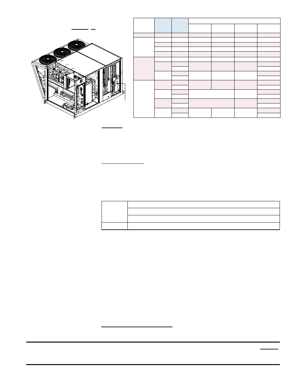
Approximate R410-A Refrigerant
Charge (lbs) for MAPS
®
III Models
by Size and Compressor for Each
Circuit
Cabinet
RCB/
RDCB/
RECB
RDB/
RDDB/
REDB
R410-A Charge (lbs) by Compressor Circuit
A
B
C
DH (Reheat)
A
060
084
4.3
4.0
N/A
4.2
A or B
078
102
5.2
4.0
N/A
4.2
090
114
5.7
4.8
N/A
4.2
118
142
6.5
4.8
N/A
4.2
136
162
6.5
5.7
N/A
4.2
B
160
184
6.5
4.8
4.2
4.2
186
210
5.2
6.0
5.2
4.2
222
6.0
200
224
5.2
6.0
6.0
4.2
236
6.0
C
190
248
8.0
10.5
N/A
9.5
262
10.0
216
272
11.0
8.5
9.5
288
10.0
298
354
11.0
11.0
9.5
370
10.0
410
468
10.5
10.5
10.5
9.5
482
10.0
Compressor B
Compressor C
Compressor A
Compressor
Dh (Reheat)
•
Step 10. System Startup
Assure voltage to compressor does not drop below minimum allowable voltage
(e.g. 187 volts for 230/208-3-60, 415 volts for 460/3/60, 518 volts for 575/3/60)
during the period the compressor is trying to start.
If a low voltage or voltage
imbalance condition exists, the electrical problem must be determined and
corrected prior to operating the unit.
Voltage Imbalance - Voltage imbalance is becoming a more common problem.
In a 3-phase system, excessive voltage imbalance between phases will cause
motors to overheat and compressors to fail. Maximum allowable imbalance is
2%. To determine voltage imbalance, measure and record the voltage of all three
phases. Take the measurements at the compressor terminals with the compressor
operating.
Voltage Imbalance Formula:
Key:
V1, V2, V3 = line voltages as measured
VA (Average )= (V1 + V2+ V3) / 3
VD = Line Voltage (V1, V2, or V3 that deviates farthest from average (VA)
Formula:
% of Voltage Imbalance = [100 (VA - VD)] / VA
If the imbalance is within the 2% tolerance, voltage imbalance is not a problem and
the system may be operated. If the imbalance exceeds the 2% tolerance, follow
the procedures below.
Solutions to Voltage Imbalance:
The cause for a voltage imbalance problem can originate at the power company or
can be caused inside the building. Try the following on-site solution to determine if
the problem can be easily resolved.
Roll the connections at the compressor terminals one forward. Connect the wire
now on Terminal 1 to Terminal 2, 2 to 3, and 3 to 1. Re-measure and re-calculate
the voltage imbalance. If the imbalance is within 2%, the system may be operated.
If the imbalance is not within tolerance, roll the connections one more forward.
Re-measure and re-calculate the voltage imbalance. If the imbalance is within
2%, the system may be operated. If the voltage imbalance still exceeds 2%, do
not start the system. Contact the building owner or person responsible to have an
electrician analyze the buildings's power supply and load distribution.
Power Supply Voltage Phasing - Connect refrigerant pressure gauges to the
suction and discharge lines of the compressors and an electric meter to the power
supply.
CAUTION: Be sure to connect pressure gauges to the suction and discharge lines before
system startup so that compressor rotation can be checked immediately. Scroll compressors
will be destroyed if allowed to operate in the wrong direction. See Hazard Levels, page 3.