0 maintenance/ service procedures (cont'd), 6 compressor maintenance (cont'd), Iv models by size and compressor for each circuit – Reznor MAPS - A,B,C Users Manual User Manual
Page 16
Form O-MAPSIII&IV Cabinets A/B/C, Page 16
•
Step 8. Check the Electrical System
After the system has been evacuated, reconnect the electrical plug to the
compressor or the wires to the compressor terminals. It is a normal practice to
replace all starting components any time a compressor is changed.
WARNING
Do not apply voltage to the compressor when the plug is
removed or terminals disconnected.
Crankcase Heater - Connect the crankcase heater. The crankcase heater is
energized continuously and is extremely important to proper compressor operation
and long life.
NOTE: See crankcase heater P/N's on page 12.
The crankcase heater must be energized for at least 24 hours before starting
the unit or after a power outage of more than 8 hours. Be sure to disable cooling
controls before turning on power to warm up crankcase heaters.
3.6 Compressor
Maintenance
(cont'd)
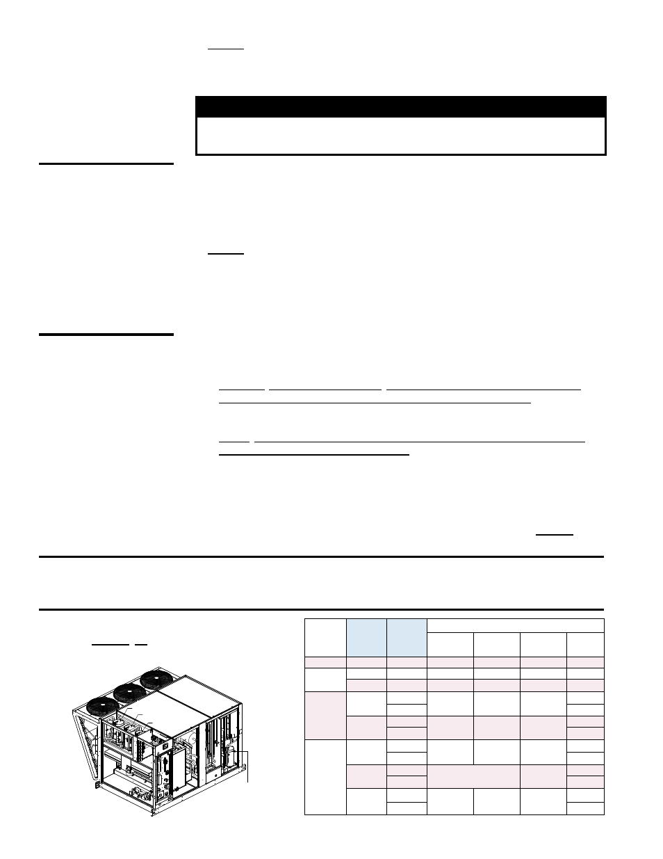
Approximate R410-A Refrigerant Charge
(lbs) for MAPS
®
IV Models by Size and
Compressor for Each Circuit
Cabinet
RCC/
RDCC/
RECC
RDC/
RDDC/
REDC
R410-A Charge (lbs) by Compressor Circuit
A
B
C
DH
(Reheat)
A
060
084
N/A
8.0
N/A
4.2
A or B
090
114
N/A
10.5
N/A
4.2
120
144
8.0
8.0
N/A
4.2
B
160
184
9.5
9.5
N/A
4.2
196
4.2
200
236
5.5
6.0
5.5
6.0
257
6.0
C
190
248
9.0
10.5
N/A
10.0
262
10.0
298
354
11.0
11.0
10.0
370
10.0
410
468
10.5
10.5
10.5
10.0
482
10.0
Compressor B
Compressor C
Compressor A
Compressor
Dh (Reheat)
3.0 Maintenance/
Service
Procedures
(cont'd)
CAUTION:
Crankcase heaters
must be allowed
to warm up for
at least 24 hours
prior to startup.
Disable cooling
controls before
turning on power
to warm up
crankcase heaters.
•
Step 9. Charge the System (Use R-410A refrigerant only.)
Refer to the applicable table (either MAPS
®
III or MAPS
®
IV) for the approximate
amount of refrigerant required. Follow the instructions below to charge the circuit.
R-410A refrigerant MUST BE charged as a LIQUID.
NOTE: Outdoor temperature must be between 70-95°F (21-35°C) for verifying
superheat and subcooling. If temperature is not within this range, consult the
factory service department before charging.
If equipped with an optional hot gas bypass, disable the hot gas bypass valve
before charging. Method of disabling depends on the model and date of
manufacture.
All MAPS
®
IV Models & any MAPS
®
III Models with a shutoff valve in the line
between the compressor discharge and the hot gas bypass valve - Locate the
shutoff valve. Disable the hot gas bypass valve by closing the shutoff valve.
When measurements are complete, be sure to open the valve.
MAPS
®
III Models without a shutoff valve in the line between the compressor
discharge and the hot gas bypass valve - Disable the hot gas bypass valve by
removing the cover and adjusting the spring tension counterclockwise until the
spring tension is relieved.
Count and record the number of turns required so
that you can return the bypass valve to its original setting. To check setting, refer
to Paragraph 3.9.5.
Liquid charge the high side to 80%. With the system running, add the balance of
the charge to the correct superheat and subcooling values. Refer to
Step 11, page
17, and the instructions in Paragraph 3.5, page 9.
IMPORTANT: Do not release refrigerant to the atmosphere! If required service
procedures include the adding or removing of refrigerant, the qualified HVAC service
technician must comply with all federal, state or provincial, and local laws.