Reznor MAPS - A,B,C Users Manual User Manual
Page 23
Form O-MAPSIII&IV Cabinets A/B/C, P/N 257004R8, Page 23
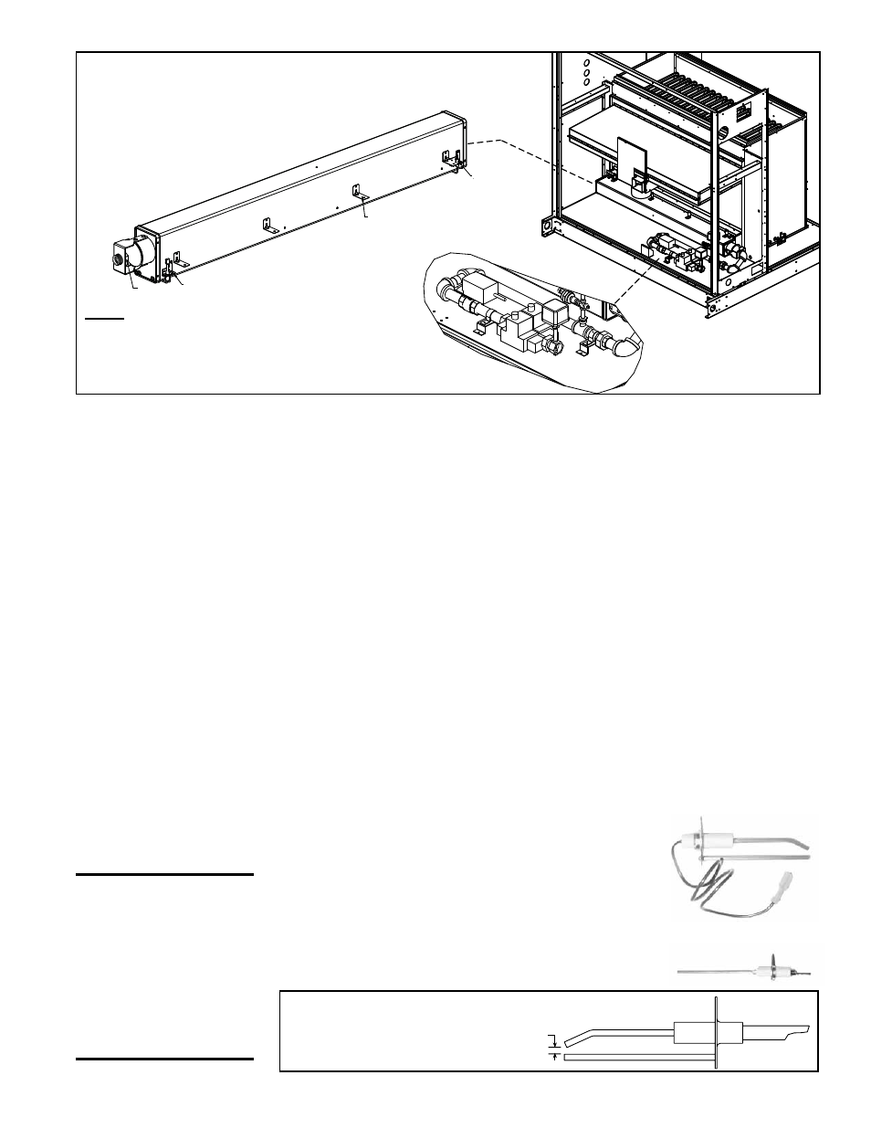
Flame
Sensor
Burner
Supports
Ignitor Assembly
Orifice
Burner Assembly
Gas Train
FIGURE 11 - Heat Section showing Burner
Assembly and Gas Train
NOTE: A "C" Cabinet heat section is illustrated.
Appearance will vary by Cabinet and size.
Maintenance requirements apply to all heat
sections including an optional curb duct furnace
(JHUP 250 or 300).
With the burner assembly removed, shine a flashlight on the burner ribbons. Look for
carbon buildup, scale, dust, lint, and/or anything that might restrict flow through the
spaces between the burner ribbons. Holding the burner assembly so that any foreign
material will fall away from the burner, use a stiff bristle brush to loosen and remove
any foreign material(s). If the burner is excessively dirty, remove both of the burner end
caps. Remove the screws that hold the end caps to the burner housing and lightly tap
end caps to remove.
Clean all foreign material from the burner and venturi. After the burner is thoroughly
cleaned, replace the end caps making certain that they are tight against the burner
housing.
Inspect and
Clean the Burner
Inspect the Lower
Portion of the Heat
Exchanger (with
burner assembly
removed)
At the burner flame entrance of each tube, shine a bright light into each heat exchanger
section. With the light shining into the heat exchanger, observe the outside for visible
light. Repeat this procedure with each heat exchanger section. If any light is observed,
replace the heat exchanger.
Burner Orifice
The burner orifice usually will not need to be replaced. If ordering a replacement orifice
only, give BTUH content and specific gravity of gas, as well as the model and serial
number of the unit and the orifice size. When removing or replacing the burner orifice
be careful not to damage the venturi tube and/or the bracket.
NOTE: If any of the
burner components
are damaged or
deteriorated, replace
the burner assembly.
Check the Ignitor and
Flame Sensor
Flame Sensor
FIGURE 12 - Ignitor
showing required Spark
Gap Measurement
1/8 inch
(3.2mm)
Ignitor - Locate the ignitor. Disconnect the wire; remove the
screw and the ignitor. Clean the ignitor assembly with an
emery cloth.
Spark gap must be maintained to 1/8". See
FIGURE 12.
IMPORTANT: When re-assembling, the brown ground wire
must remain attached to the ignitor.
Flame Sensor - Locate the flame sensor on the burner. Dis-
connect the wires; remove the screws and the flame sensor.
Clean with an emery cloth.
Ignitor
CAUTION: Due
to high voltage
on the spark wire
and electrode, do
not touch when
energized. See
Hazard Levels,
page 3.