0 maintenance/service procedures (cont'd), Iii models, Iv models modulating cooling - maps – Reznor MAPS - A,B,C Users Manual User Manual
Page 12: Iv models
Form O-MAPSIII&IV Cabinets A/B/C, Page 12
3.0 Maintenance/Service Procedures (cont'd)
3.6 Compressor Operation, Maintenance, and Replacement (cont'd)
208-240/3/60
480/3/60
575/3/60
Compressor
Crankcase
Heater P/N
Compressor
Crankcase
Heater P/N
Compressor
Crankcase
Heater P/N
Model
P/N
Model
P/N
Model
P/N
ZP24K5E
235095
216434
ZP24K5E
235097
216436
ZP24K5E
235099
216437
ZP36K5E
235096
216398
ZP36K5E
235098
216400
ZP36K5E
235100
216401
ZP54K5E
235008
216398
ZP54K5E
235012
216400
ZP54K5E
235016
216401
ZP57K3E
216686
216398
ZP57K3E
216687
216400
ZP57K3E
216688
216401
ZP72KCE
235009
216398
ZP72KCE
235013
216400
ZP72KCE
235018
216401
ZP83KCE
216689
216398
ZP83KCE
216690
216400
ZP83KCE
216691
216401
ZP137KCE
235010
216398
ZP137KCE
235014
216404
ZP137KCE
235019
216405
ZPT144KCE
235011
216398
ZPT144KCE
235015
216400
ZPT144KCE
235020
216401
ZP154KCE
220260
216402
ZP154KCE
220261
216404
ZP154KCE
220262
216405
Compressors and Crankcase Heater P/N's by Voltage on MAPS
®
III Models
208-240/3/60
480/3/60
575/3/60
Compressor
Crankcase
Heater P/N
Compressor
Crankcase
Heater P/N
Compressor
Crankcase
Heater P/N
Model
P/N
Model
P/N
Model
P/N
ZP24K5E
235095
216434
ZP24K5E
235097
216436
ZP24K5E
235099
216437
ZP36K5E
235096
216394
ZP36K5E
235098
216396
ZP36K5E
235100
216397
ZP54K5E
235008
216394
ZP54K5E
235012
216396
ZP54K5E
235016
216397
ZP57K3E
216686
216398
ZP57K3E
216687
216400
ZP57K3E
216688
216401
ZP61KCE
261235
216398
ZP61KCE
261236
216400
ZP72KCE
235018
216401
*ZPD61KCE
261145
216398
*ZPD61KCE
261146
216400
ZP83KCE
216691
216401
ZP72KCE
235009
216398
ZP72KCE
235013
216400
*ZPD83KCE
261149
216401
ZP83KCE
216689
216398
ZP83KCE
216690
216400
ZP137KCE
235019
216405
*ZPD83KCE
261147
216398
*ZPD83KCE
261148
216400
*ZPD137KCE
261155
216405
ZP137KCE
235010
216402
ZP137KCE
235014
216404
*ZPD61KCE
268531
216401
*ZPD137KCE
261153
216402
*ZPD137KCE
261154
216404
ZP61KCE
268532
216401
ZP154KCE
220260
216402
ZP154KCE
220261
216404
*ZPDT14MCE
268533
216401
*ZPDT14MCE
262656
(2)
216398
*ZPDT14MCE
262657
(2)
216400
* Modulating capacity compressor
Compressor and Crankcase Heater P/N's by Voltage on MAPS
®
IV Models
Modulating Cooling -
MAPS
®
IV Models
MAPS
®
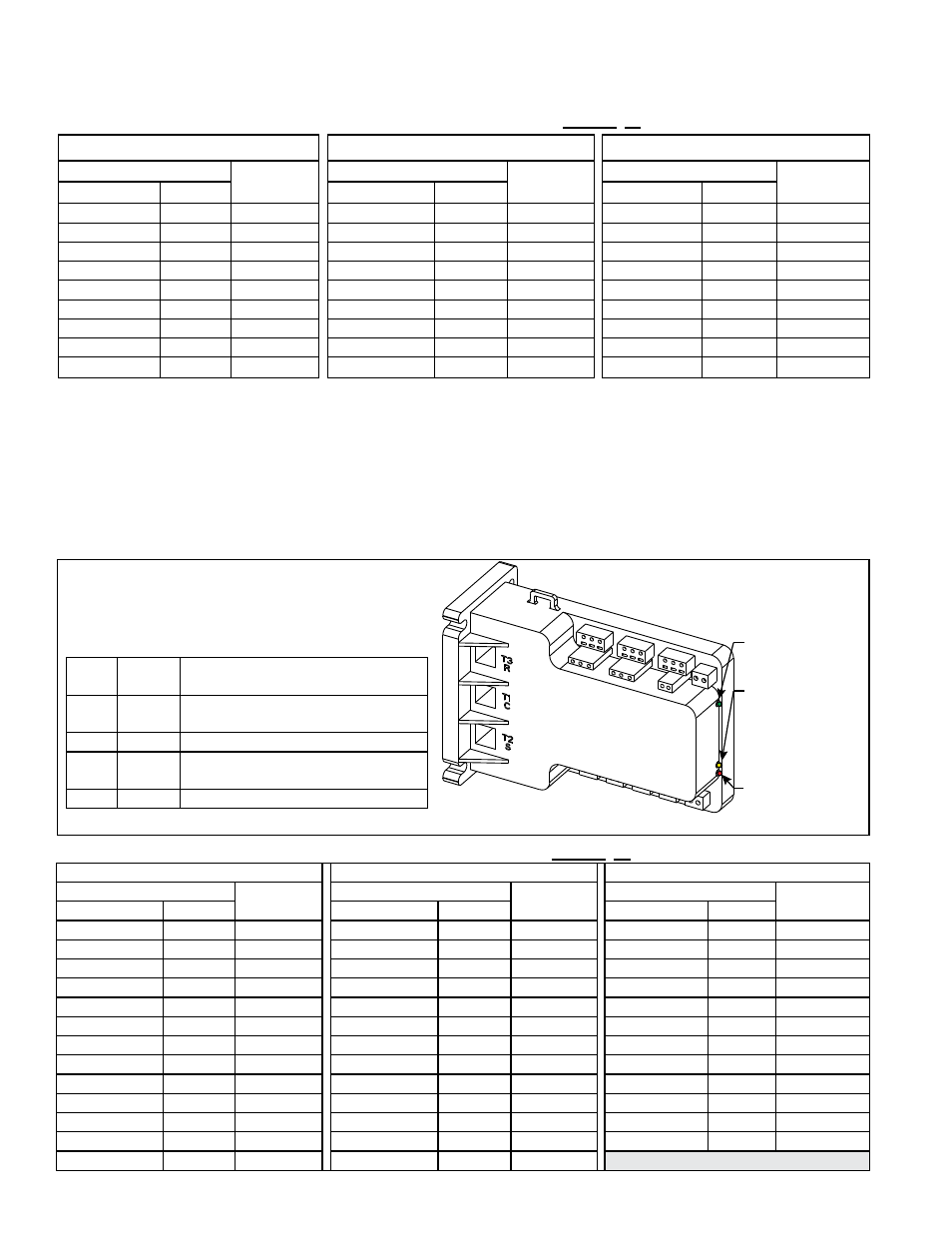
IV units are equipped with a modulating capacity compressor and a digital con-
troller to provide cooling modulation. The digital controller in the control compartment
(See
FIGURE 1, page 5) is the electronic interface between the compressor and the
system controller. The compressor controller is connected to the unit controller to pro-
vide protection and diagnostics for modulating compressor operation.
After a compressor shutdown, a two-minute anti-short cycle timer in the compressor
controller delays the compressor restart. The unit controller has a five-minute compres-
sor on/off time. The delay times are concurrent so total delay time is five minutes.
Alarm Light
(Red LED) - See
Paragraph 7.2.
Compressor
Modualting
Solenoid Valve
Energized Light
(Yellow LED)
Power Light
(Green LED)
FIGURE 5 - Compressor Digital Controller
located in the control compartment
interfaces the modulating capacity
compressor with the unit controller.
LED
Color
LED
State
Indicates
Green Solid
Power (24VAC present at power
terminals)
Green Flashing Anti-short cycle timer is active
Yellow Solid
Unloader (Solenoid valve is
energized; compressor capacity is 0.)
Red
Not lit
No abnormal operation alerts
NOTE: See Troubleshooting, Paragraph 7.2.
NOTE: To identify MAPS
®
IV
Models, see Paragraph 1.0.