Reznor MAPS - A,B,C Users Manual User Manual
Page 39
Form O-MAPSIII&IV Cabinets A/B/C, P/N 257004R8, Page 39
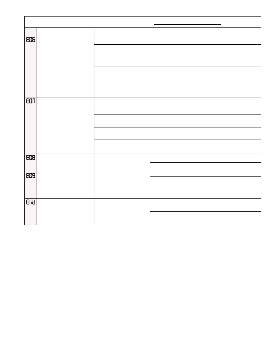
Gas Heat Section Modulating Control LOCKOUT ERRORS (cont'd)
Code
Alert
Description
Probable Causes
Solutions
Gas
Sensor
Failure
(EO6)
Pressure
Sensor
Reading
Low
The gas transducer
reading is too low
compared to the
expected value for the
modulating gas valve
actuator position.
When the furnace is
operating at 75% or
higher -- greater than
8 VDC analog input
voltage - the manifold
pressure sensor must
read 1.4" w.c. or
higher
A. Modulating actuator/ball valve
not properly aligned
1 Perform modulating system gas valve alignment procedure; see
Paragraph 4.3.
B. Line pressure too low
1. Ensure line pressure is properly adjusted for the gas and
application. Correct as needed.
C. Intermediate regulated
pressure to low
1. Ensure the safety gas valve(s) are properly adjusted to the
specified outlet pressure. Adjust per the installation instructions as
necessary.
D. Wrong gas pressure sensor
installed.
1. Ensure the proper gas transducer - either natural gas or propane
- is installed. Replace as needed.
E. Gas pressure sensor faulty
1. Ensure gas manifold transducer is installed properly and wired
per the unit wiring diagram. Replace as necessary.
Gas
Sensor
Failure
(EO7)
Pressure
Sensor
Reading
High
The gas transducer
reading is too high
compared to the
expected value for the
modulating gas valve
actuator position.
When the furnace
is operating at 75%
or lower - less than
8 VDC analog input
voltage -- the manifold
pressure sensor must
read 2.8" w.c. or lower.
A. Modulating actuator / ball
valve not properly aligned
1. Perform modulating system gas valve alignment procedure; see
Paragraph 4.3.
B. Line pressure too high
1. Ensure the line pressure is properly adjusted for the gas and
application. Correct as necessary.
C. Intermediate regulated
pressure too high
1. Ensure the safety gas valve(s) are properly adjusted to the
specified outlet pressure. Adjust per the installation instructions as
necessary.
D. Wrong gas pressure sensor
installed
1. Ensure gas sensor -- either natural or propane -- is installed.
Replace as necessary.
E. Gas pressure sensor faulty
1. Ensure gas sensor is installed properly and wired per the unit
wiring diagram. Replace as necessary.
Improper
Flame
Signal
(EO8)
Control senses flame
present when the gas
valve is commanded
off.
A. Flame remains lit in “Off” cycle 1. Gas valve leaks - check wiring to remove continuous 24V to gas
valve.
2. Gas valve is stuck open – remove, repair, or replace gas valve.
No Firing
Rate Input
(EO9)
Call for heat is sensed
(R & W closed) but
firing rate is below
defined voltage
threshold for furnace
operation.
A. Faulty wiring into the “Analog
+” and “Analog –“ terminals
1. Ensure wiring is connected per unit wiring diagram.
2. Check for loose pins or bad connections.
3. Check for frayed wiring or shorts to ground.
B. No signal from source.
1. Check firing rate input voltage – must be greater than 1.5 VDC.
2. Troubleshoot controller providing firing rate input to the deep
modulation ignition control board.
Invalid I.D.
Plug (Eid)
The installed I.D. plug
is not valid for this
control board.
A. Incorrect I.D. plug installed
1. Ensure I.D. plug is correct for the furnace – check label.
2. Ensure I.D. plug is properly inserted into the mating connector on
the control board.
3. With the I.D. plug installed, cycle power to the furnace. The board
will display the I.D. plug identity upon power-up.
4. Install correct I.D. plug as needed.