Reznor MAPS - A,B,C Users Manual User Manual
Page 37
Form O-MAPSIII&IV Cabinets A/B/C, P/N 257004R8, Page 37
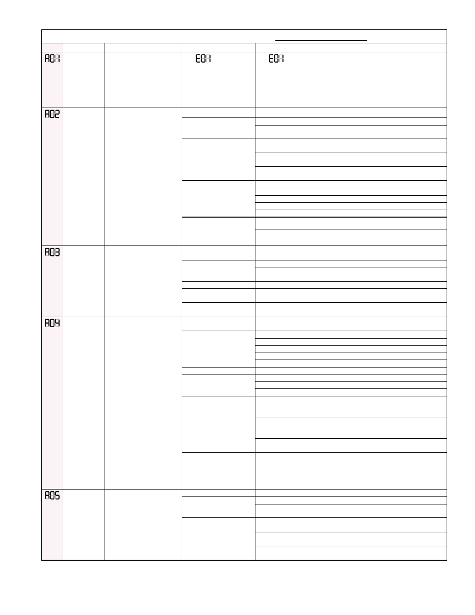
Gas Heat Section Modulating Control FUNCTIONAL ALERTS
Code
Alert
Description
Probable Causes
Solutions
Failed ignition
attempt (AO1)
Maximum
number of
allowed retries
not met
The flame could not be
established during the trial
for ignition period. This alert
indicates the maximum
number of retries has not
been exceeded and furnace
operation will continue with
another ignition attempt.
See
in the
LOCKOUT ERRORS
section, pages 38-39.
See
in the LOCKOUT ERRORS section, pages 38-39.
Lost Flame
(AO2)
The flame sensor signal
has been lost after flame is
established during a call for
heat. This alert is displayed
during the RECYCLE period
prior to the next ignition
attempt.
A. Flame sensor coated
1. Clean flame rod sensor.
B. Flame sensor
improperly mounted or
grounded
1. Check flame sensor wiring integrity and ceramic for cracks.
2. Re-install / replace flame sensor.
C. Unstable flame pattern 1. Verify that the spacing between the burner body and the burner shield
is equal across the entire length of the burner.
2. Check that the seals between the heat exchanger header and heat
exchanger tubes are sound; refer to Paragraph 4.1.1.
3. Ensure that the heat section door gasket is in place and the doors are
properly aligned
D. Insufficient intermediate
gas manifold pressure
through main gas safety
valve
1. Check for faulty gas valve wiring.
2. Check 24 VAC to gas valve assembly.
3. Check inlet pressure to safety gas valve.
4. Check outlet pressure from the safety gas valve.
5. Replace safety gas valve if faulty.
E. Insufficient gas manifold
pressure to burner through
modulating ball valve
assembly
1. Check voltage to gas valve actuator. (2-10 VDC depending on model)
2. Check alignment and set screw connection between ball valve and
actuator. See Paragraph 4.3.
Insufficient
Combustion Air
(AO3)
Furnace
functional
Furnace cannot achieve
desired combustion air flow
due to blockage or high
altitude operation resulting in
a de-rate of the furnace.
A. High altitude operation
1. Normal operation. Furnace automatically de-rates for high altitude
conditions.
B. Partially blocked vent
1 Check air inlet and outlet for blockage.
2. Check venting configuration for excessive venting length, improper
sizing, etc.
C. Leak in sensing hose
1. Check sensing hose for cracks, crimps, or loose connections.
D. Low Line Voltage
1. Check the line voltage to the control board. Voltage should be within
10% of nameplate.
E. Faulty venter assembly 1. Verify that the venter assembly is functioning properly by referring to
the sensing pressure chart on page 30.
Limited Low
Fire (AO4)
Automatic adaptive program
is currently limiting the lower
range of modulation at avoid
flame loss at minimum fire
conditions. The alert is
displayed during the run
cycle once a flame-out
condition has triggered the
Limited Low Fire function.
This function is reset by
cycling power to the board.
A. Low gas line pressure
1. Ensure gas supply is connected to furnace and check for proper line
pressure.
B. Insufficient intermediate
gas manifold pressure
through gas safety valve
1. Check for faulty gas valve wiring.
2. Check 24 VAC to gas valve assembly.
3. Check inlet pressure to safety gas valve.
4. Check outlet pressure from the safety gas valve – adjust as needed.
5. Replace safety gas valve if faulty.
C. Faulty burner operation 1. Check burner orifice for proper size and blockage.
D. Faulty flame sensor
1. Check flame rod wiring and connections.
2. Check for proper alignment of flame rod.
3. Clean flame rod sensor.
E. Improper alignment of
the modulating actuator
and the gas ball valve.
1. Check that the alignment of the actuator to the ball valve is correct.
The valve must be in the fully open position when the actuator is
energized (ACTUATOR DRIVE = 9.6 VDC or greater).
2. Ensure that the setscrew on the actuator is tightened to the ball valve
stem.
F. Blocked or improper
venting
1. Check air inlet and outlet for blockage.
2. Check venting configuration for excessive venting length, improper
sizing, etc.
G. Improper jumper
connection on IQ UI-12
causing AO-4 to show on
BacView as alarm and
disables heat sequence.
1. Verify that the IQ heating feedback input is set to receive the ignition
board voltage output of 0-10VDC from terminals J7 by making sure
jumpers are set to receive 0-10VDC signal on UI-12 of the IQ controller.
Weak Flame
Signal (AO5)
The flame signal level is
less than optimal for this
furnace. Maintenance of the
flame sensing components
is advised.
A. Flame sensor coated
1. Clean flame rod sensor.
B. Flame sensor
improperly mounted or
grounded
1. Check flame sensor wiring integrity and ceramic for cracks.
2. Re-install / replace flame sensor.
C. Unstable flame pattern 1. Verify that the spacing between the burner body and the burner shield
is equal across the entire length of the burner.
2. Check that the seals between the heat exchanger header and heat
exchanger tubes are sound; refer to Paragraph 4.1.1.
3. Ensure that the heat section door gasket is in place and the door is
properly aligned.
(continued)