4 other gas heat section controls / sensors, 0 electric heat section maintenance, Recb, recc, redb, redc -31 – Reznor MAPS - A,B,C Users Manual User Manual
Page 30
Form O-MAPSIII&IV Cabinets A/B/C, Page 30
4.4 Other Gas Heat Section Controls / Sensors
Location: See FIGURE 1, page 5, for location.
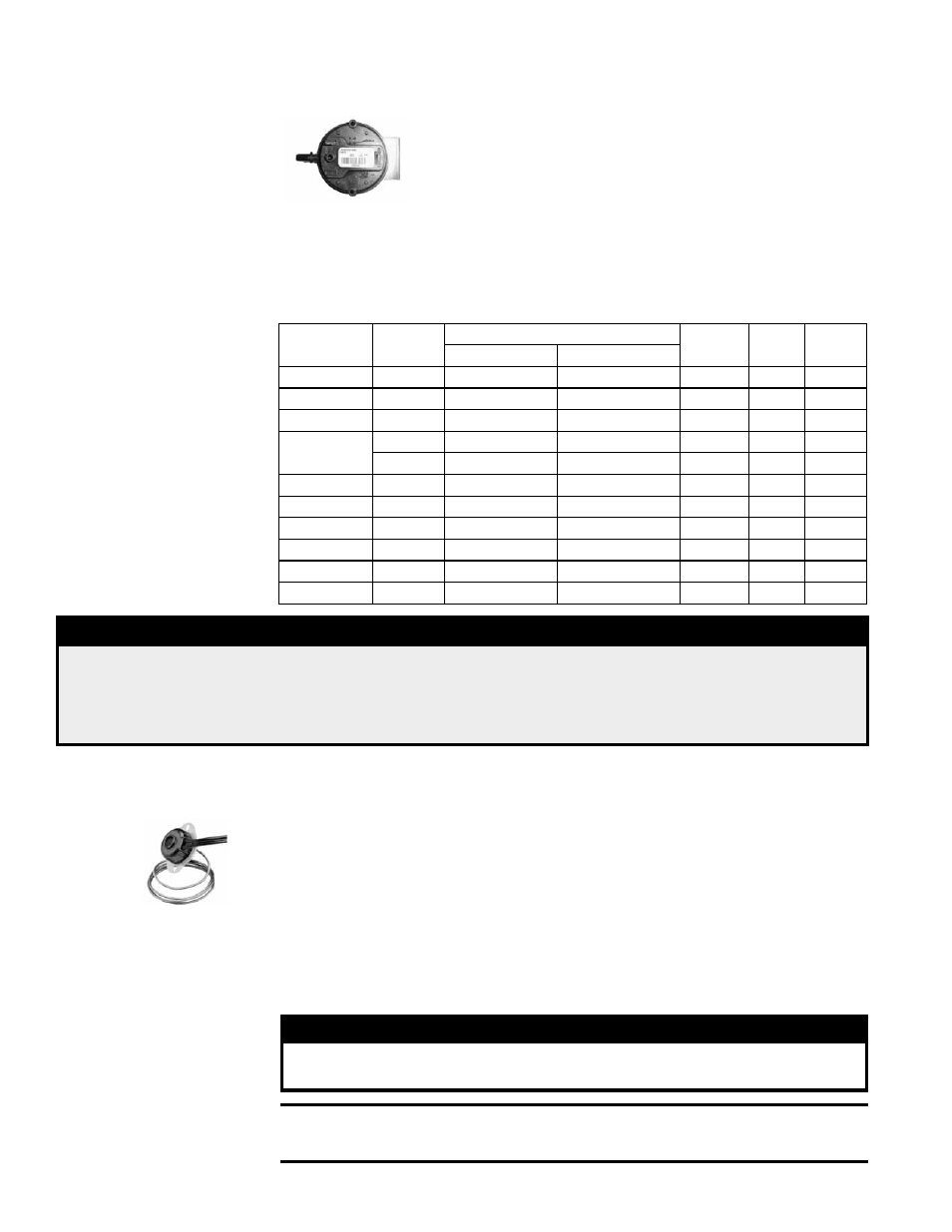
Function: The function of the pressure switch is to verify the cali-
bration of the air pressure sensor mounted on the ignition control
board. If the air pressure is not as required, the controller will shut
down operation of the heat section.
Service: If it is determined that the pressure switch needs replacing, use only the
factory-authorized replacement part that is designed for the model and size of gas
heater being serviced.
Combustion Air Proving Switch
The ignition board controls the entire combustion process by modulating both the gas
and the combustion air supply. Combustion air pressure switches used are listed below.
Heat Section
Size
Gas
Full Rate
Setpoint
OFF
Label
Color
Switch
P/N
Light Off (Cold) Equilibrium (Hot)
100
Nat & Pro
1.30
1.30
0.80
Gray
197078
150
Nat & Pro
1.30
1.30
0.80
Gray
197078
200
Nat & Pro
1.30
1.30
0.80
Gray
197078
250 and
JHUP-250
Natural
1.15
1.15
0.80
Gray
197078
Propane
1.30
1.30
1.05
Brown 201160
300
Nat & Pro
1.40
1.40
1.15
Brown 201160
400
Natural
2.70
2.70
1.40
Red
201159
500
Natural
2.90
2.90
1.40
Red
201159
600
Natural
3.35
3.35
2.00
White 234054
700*
Natural
3.40
3.40
2.00
White 234054
JHUP-300*
Natural
0.70
0.70
0.50
Orange 196388
□ *A "B" Cabinet with 500
mbh of gas heat is a Size
250 heat section plus
a Model JHUP-25 curb
section duct furnace.
Both furnaces have an
air proving switch.
□ ** A "C" Cabinet with
1000 mbh of gas heat is
a Size 700 heat section
plus a Model JHUP-30
curb section duct fur-
nace. Both furnaces
have a combustion air
proving switch.
Limit Control
Location: The limit control is located in the farthest downstream heater compartment
with the capillary sensor extending across the discharge side of the heat exchanger.
NOTE: If the installation includes an Option JHUP-30 curb section duct furnace, it also
has a limit control. See location in installation Form I-MAPSIII&IV, Paragraph 5.4.3
Function: The limit control is a temperature sensitive safety device. If the temperature
setting of the limit control is exceeded, the controller will shut down heat section opera-
tion.
Service: The limit switch will automatically reset when the temperature drops below
the setpoint. However, the cause for the limit activating should be found and corrected.
If it is determined that the limit control needs replacing, use only a factory-authorized
replacement part that is designed for that heat section.
5.0 Electric Heat
Section
Maintenance -
Models RECB,
RECC, REDB
and REDC
4.0 Gas Heat
Section
Maintenance
(cont'd)
DANGER
Safe operation requires proper venting flow. Never bypass the combustion air
proving switch or attempt to operate the heat section without the venter running
and proper flow in the vent system. Hazardous condition could result. See Hazard
Levels, page 3.
WARNING
Turn off the power locking the disconnect switch. Allow the
heating elements to cool.
CAUTION: Wearing eye protection is recommended when
cleaning the heating elements and cabinet.