Reznor MAPS - A,B,C Users Manual User Manual
Page 35
Form O-MAPSIII&IV Cabinets A/B/C, P/N 257004R8, Page 35
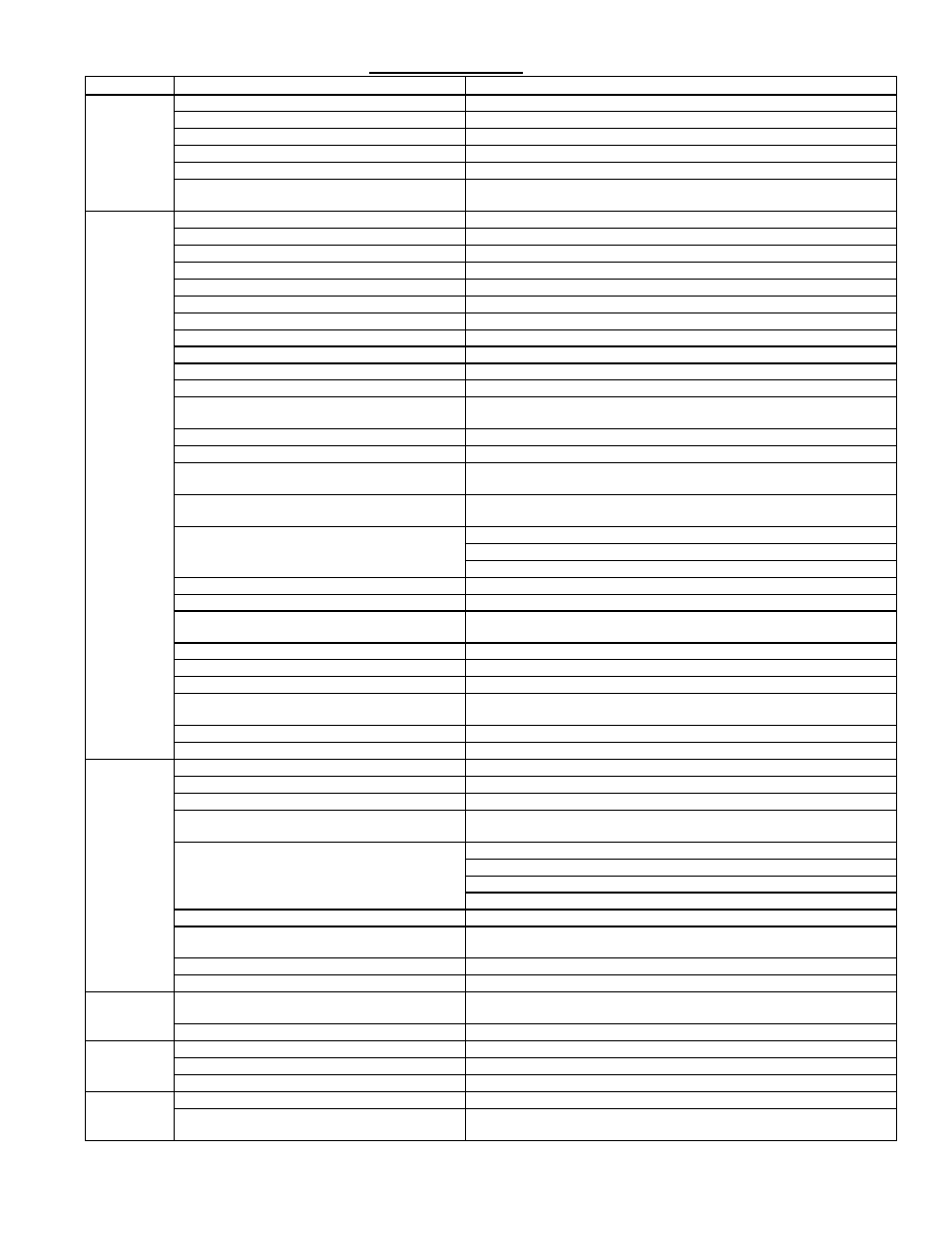
7.3.2 General Troubleshooting - Gas Heat Section - Models RDCB, RDCC, RDDB & RDDC
PROBLEM
PROBABLE CAUSE
REMEDY
Venter motor
will not start
1. No power to unit.
1. Turn on power; check supply fuses or main circuit breaker.
2. No 24 volt power to ignition system circuit board. 2. Turn up thermostat; check control transformer output.
3. Integrated circuit board fuse blown.
3. Correct cause; replace fuse.
4. No power to venter motor.
4. Tighten connections at circuit board and/or motor terminals.
5. Integrated circuit board defective.
5. Replace integrated circuit board.
6. Defective venter motor or capacitor
6. Replace defective parts. Recommend replacing capacitor when replacing
motor. See Paragraph 4.1.2.
Burner will
not light
1. Manual valve not open.
1. Open manual valve.
2. Air in the gas line.
2. Bleed gas line (initial startup only).
3. Gas pressure too high or too low.
3. See installation manual, Form I-MAPSIII&IV, Paragraph 9.2.1.
4. No Spark:
4.
a) Loose wire connections.
a) Be certain all wire connections are solid.
b) Transformer failure.
b) Be sure 24 volts is available.
c) Incorrect spark gap.
c) Maintain spark gap at 1/8".
d) Spark cable shorted to ground.
d) Replace worn or grounded spark cable.
e) Spark electrode shorted to ground.
e) Replace if ceramic spark electrode is cracked or grounded.
f) Burner not grounded.
f) Make certain circuit board is grounded to ignitor.
g) Ignition system circuit board not grounded.
g) Make certain circuit board is grounded to furnace chassis.
h) Unit not properly grounded.
h) Make certain unit is properly field grounded to earth ground and properly
phased (L1 to hot lead L2 to neutral).
i) Ignition system circuit board fuse blown.
i) Correct cause; replace fuse.
j) Modulation system out of acceptance range
j) Review error codes on board; refer to pages 36-39.
j) Faulty circuit board.
j) If 24 volt is available to the circuit board and all other causes have been
eliminated, replace board.
5. Lockout device interrupting control circuit by
above causes.
5. Reset lockout by interrupting control.
6. Combustion air proving switch not closing
6.
a) Remove obstructions from vent.
b) Replace faulty tubing to pressure switch.
7. Faulty combustion air proving switch.
7. Replace combustion air proving switch.
8. Valve not operating.
8.
a) Defective valve.
a) If 24 volt is measured at the valve connections and valve remains closed,
replace valve.
b) Loose wire connections
b) Check and tighten all wiring connections.
9. Circuit board does not power valves.
9.
a) Loose wire connections.
a) Check and tighten all wiring connections.
b) Flame sensor grounded.
b) Be certain flame sensor lead is not grounded or insulation or ceramic is
not cracked. Replace as required.
c) Incorrect gas pressure.
c) See installation manual, Form I-MAPSIII&IV, Paragraph 9.2.1.
d) Cracked ceramic at sensor.
d) Replace sensor.
Burner cycles
on and off
1. Gas pressure too high or too low.
1. See installation manual, Form I-MAPSIII&IV, Paragraph 9.2.1.
2. Burner not grounded
2. Make certain integrated circuit board is grounded to ignitor.
3. Circuit board not grounded.
3. Make certain integrated circuit board is grounded to furnace chassis.
4. Faulty integrated circuit board
4. If 24 volt is available to the circuit board and all other causes have been
eliminated, replace board.
5. Combustion air proving switch not closing.
5.
a) Make sure unit is properly vented.
b) Remove obstructions from vent.
c) Replace faulty tubing to pressure switch.
6. Faulty combustion air proving switch.
6. Replace combustion air proving switch.
7. Flame sensor grounded.
7. Be certain flame sensor lead is not grounded or insulation or ceramic is
not cracked. Replace as required.
8. Cracked ceramic at sensor.
8. Replace sensor.
9. Incorrect polarity.
9. Reverse line volt leads to integrated circuit board.
No heat
(Heater
Operating)
1. Incorrect valve outlet pressure.
1. Check valve outlet pressure. See Installation Form I-MAPSIII&IV,
Paragraph 9.2.1.
2. Cycling on limit control.
2. Check air throughput.
Venter motor
will not run
1. Circuit open.
1. Check wiring and connections.
2. Defective integrated circuit board.
2. Replace board.
3. Defective motor.
3. Replace motor.
Venter motor
cuts out on
overload
1. Low or high voltage supply.
1. Correct electric supply.
2. Defective motor or capacitor.
2. Replace defective parts. Recommend replacing capacitor when replacing
motor. See Paragraph 4.1.2.