0 maintenance/ service procedures (cont'd), 9 other controls, 8 optional dampers and damper controls – Reznor MAPS - A,B,C Users Manual User Manual
Page 20
Form O-MAPSIII&IV Cabinets A/B/C, Page 20
Refer to Control
Instruction Form
CP-MAPS D15/16/17/18
for information on the
programmable controller.
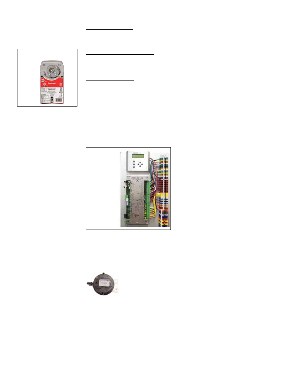
I/Q System
Controller
BACview
Display
All MAPS
®
systems have a unit-mounted,
24-volt I/Q programmable controller.
Depending on how it was ordered, the
system is equipped for either neutral air/
discharge air control (Option D15) or
space control with discharge air reset
(Option D16). In addition, MAPS
®
IV elec-
tric heat Model RECC for process appli-
cations may have neutral air/discharge
air control (Option D17) or space control
with discharge air reset (Option D18). The
controller is factory programmed to match
the selection. See the control instruction
manual, Form CP-MAPS D15/16/17/18, for
more details.
FIGURE 8 - I/Q
System Program-
mable Controller
and Unit Module
Interface with Display
3.9.3 Motor Starter
(Option AN10) or
Variable Frequency
Drive (Option VFD2)
Function: When the main controller calls for blower operation, either an IEC type
starter with a contactor or a variable frequency drive (VFD) module responds to oper-
ate the motor.
The starter is in the high voltage control compartment. The VFD was field installed in
a location that is no more than 50 feet (15M) away where the minimum temperature
is 18°F (-9°C). Control of the variable frequency drive module is coordinated with the
main controller, and depending on what was ordered, can function in response to tem-
perature, CO2, or pressure controls.
Service: If a starter or contactor need replaced, use only the identical replacements
that are designed to match the motor and voltage of the system.
3.9.2 Air Proving
Switch
Function: The airflow proving switch is a pressure switch that verifies
to the main controller that the blower is operating.
Service: If the switch needs to be replaced, use a factory-authorized
replacement designed for the application.
3.9 Other Controls
3.9.1 Programmable Digital Controller and Sensors
3.8 Optional Dampers and Damper Controls
Inlet Air Dampers
Location: Dampers and damper motors are located in the inlet air opening.
Function: Dampers operate in response to a variety of controls (GF Options).
Service: Clean dampers and controls of dust and dirt.
2-Position Damper Motor (Options AR8, AR2D, AR2L)
Function: The 2-position damper motor opens and closes the dampers in response to
unit operation or a field-supplied time clock. The motor closes the dampers on heater
shutdown.
Modulating Motor (Options AR25, AR2G, AR2H, AR2K)
Function: The modulating damper motor actuates the dampers in response to the
selected control with actuation from input switch settings.
The motor closes the inlet dampers on heater shutdown.
Service: Other than external cleaning, there is no service required on the dampers or
the damper motor. If the damper, control, or motor need to be replaced, replace with a
factory-authorized replacement.
For additional information on damper controls (Options GF 1-9), see the system instal-
lation manual Form I-MAPSIII&IV.
FIGURE 7 - Damper
Motor
3.0 Maintenance/
Service
Procedures
(cont'd)
Some sensors are standard and others will depend on option selection.
Service: If a sensor needs to be replaced, use only a factory authorized replacement
part designed for the purpose. Refer to the digital wiring requirements in Paragraph 7.4
of Installation Form I-MAPSIII&IV.
If a controller needs to be replaced, it must be replaced with the same controller and
software.