0 troubleshooting -39, 1 troubleshooting - refrigeration (all models), 0 troubleshooting – Reznor MAPS - A,B,C Users Manual User Manual
Page 32
Form O-MAPSIII&IV Cabinets A/B/C, Page 32
7.0 Troubleshooting
IMPORTANT:
Do not release refrigerant to the atmosphere!
If required service procedures include the adding or removing of
refrigerant, the service technician must comply with all federal,
state and local laws. The procedures discussed in this manual
should only be performed by a qualified HVAC technician.
NOTE: Unit is equipped with a phase loss/phase reversal control. If system
does not start, check phase of electrical supply.
7.1 Troubleshooting
- Refrigeration
(All Models)
See Control
Instructions, Form
CP-MAPSD15/16/17/18,
for information on the unit
controller.
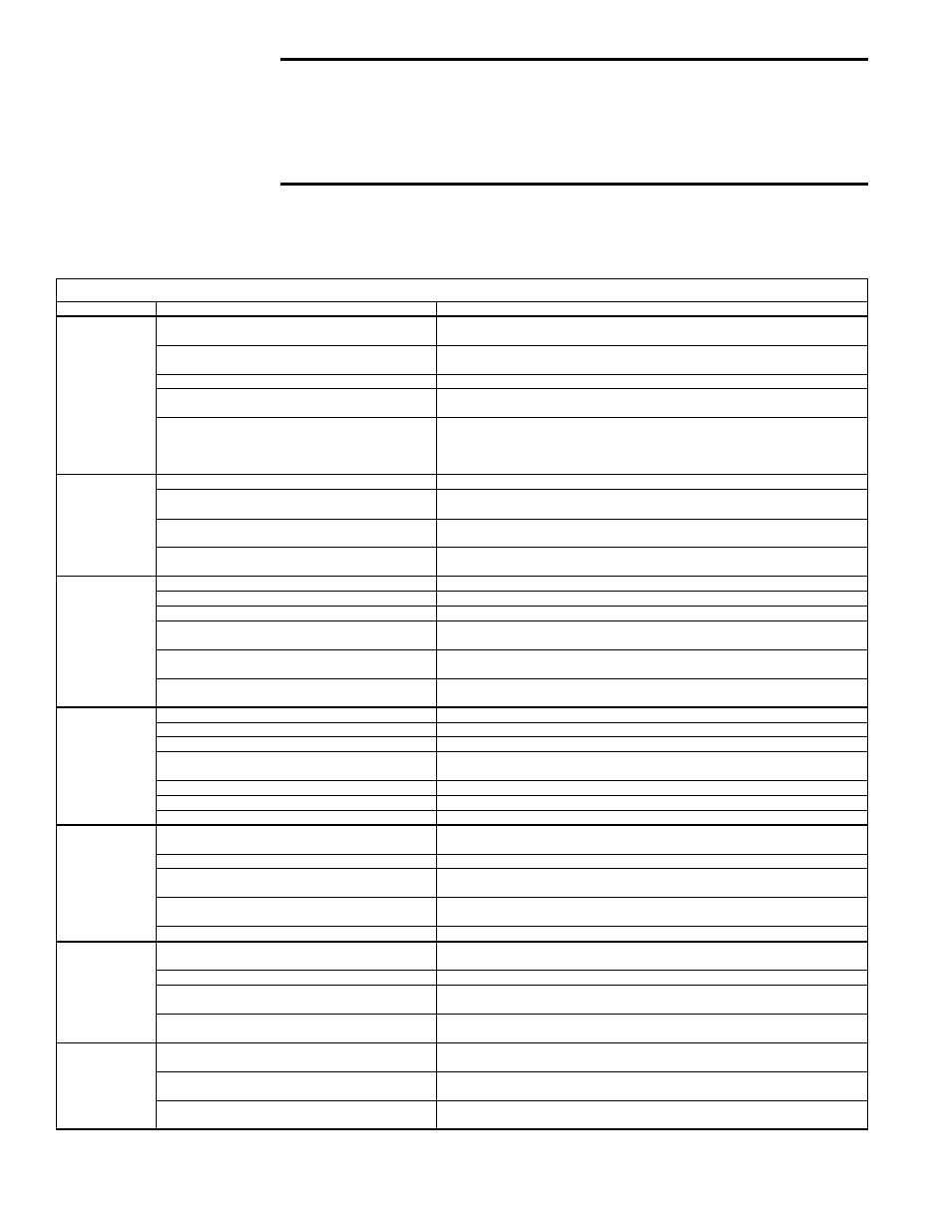
General Refrigeration Circuit - applies to all Models
SYMPTOM
POSSIBLE CAUSE
REMEDY
A. Compressor
will not start.
1. Power off, loose electrical connections or fuse
open.
1. Check disconnect switch, fuses and wiring. Replace parts or repair as
necessary
2. Compressor contactor not closing.
2. Check voltage to contactor coil, transformer, slave relay, system. Replace
parts as necessary.
3. Internal compressor thermal overload open.
3. If compressor is hot, allow 2 hours to cool. See D. below.
4. Compressor defective.
4. Check compressor for electrical failure. Compressor may be seized; check
refrigerant. If necessary, replace compressor.
5. High or low pressure switch open or defective.
5. If manual reset (high pressure), reset switch. (Switch opens at 600 psi and will
not reset above 400 psi.)
If auto reset (low pressure) does not reset and everything else is OK, replace low
pressure switch,
P/N 216380.
B. Compressor
starts but cuts out
on low pressure
(low pressure
switch activates
at 35 psig.)
1. Low refrigerant charge.
1. Check subcooling; see Paragraph 3.5.
2. Airflow restricted.
2. Check for dirty evaporator coil, dirty filters, dampers closed, iced evaporator
coil, and/or improper belt. Check motor amps. Check duct design.
3. Restriction in refrigerant line.
3. Check subcooling and superheat (Paragraph 3.5). Check operation of the
thermal expansion valve. Check for pressure drop across the filter drier.
4. Defective low pressure switch.
4. Check switch (opens 35 psi; closes 50 psi). If defective, replace low pressure
switch,
P/N 216380.
C. Compressor
starts but cuts out
on high pressure
switch.
1. Refrigerant overcharge.
1. Check subcooling; see Paragraph 3.5.
2. Condenser fan motor defective.
2. Check fan motor.
3. Condenser coil inlet obstructed or dirty.
3. Check coil and inlet clearances and for possible air recirculation.
4. Air or non-condensables in system.
4. Check high side equalized pressure reading with equivalent outdoor
temperature.
5. Defective high pressure switch.
5. Check switch (opens 600 psi; proof 700 psi; manual reset allowed below 400
psi). If defective, replace high pressure switch,
P/N 216379
.
6. Restriction in discharge or liquid line.
6. Check subcooling and superheat (Paragraph 3.5). Check operation of thermal
expansion valves.
D. Compressor
cuts out on
thermal overload.
1. Low voltage.
1. Check voltage.
2. Sustained high discharge pressure.
2. Check running amperage and conditions described in I.
3. High suction and discharge pressures.
3. Check thermal expansion valve operation, check for air in system.
4. Defective compressor overload.
4. If compressor is hot, allow compressor to cool for two hours. Recheck for
open circuit.
5. Improper refrigerant charge.
5. Check subcooling (Paragraph 3.5).
6. Bearings or pistons too tight.
6. Check for low oil level.
7. Allow time for compressor to cool.
7. Check dome temperature of the compressor.
E. Noisy
compressor.
1. Reverse rotation.
1. Check at startup. If the suction pressure rises and discharge pressure drops,
shut down the compressor. Switch the 3-phase wiring connections.
2. Refrigerant overcharge.
2. Check pressures and subcooling (Paragraph 3.5).
3. Liquid floodback.
3. Check thermal expansion valve setting. Check subcooling for refrigerant
overcharge (Paragraph 3.5).
4. Tubing rattle.
4. Dampen tubing vibration by taping or clamping. Carefully bend tubing away
from contact where possible.
5. Compressor defective.
5. Check internal parts. Replace defective parts or compressor.
F. Noisy unit
operation.
1. Blower rotational noise.
1. Check blower, motor and drive for faulty adjustment or noisy bearings, loose
parts, and/or blower out of balance.
2. Air noise.
2. Check ductwork. Air velocity too high.
3. Chattering contactor.
3. Check for adequate control voltage; check for shorts or breaks; check contact
points.
4. Tubing rattle.
4. Dampen by taping or clamping, carefully bend tubing away from contact when
possible.
G. High suction
pressure
1. Excessive load on evaporator coil.
1. Check superheat (Paragraph 3.5). Check for high entering wet bulb
temperature. Check for excessive air.
2. Compressor is unloaded.
2. Check head pressure. Check thermal expansion valve. If valve is not
functioning properly, check pressure drop across filter drier.
3. Expansion valve bulb not secured to suction line
or valve defective.
3. Check the thermal expansion valve; ensure bulb is attached properly and
insulated