Reznor MAPS - A,B,C Users Manual User Manual
Page 22
Form O-MAPSIII&IV Cabinets A/B/C, Page 22
CAUTION: Use of
eye protection is
recommended.
4.1.1 Instructions for
Inspecting/Cleaning
the Heat Exchanger
and Burner
Heat Exchanger Maintenance -
The outside of the heat exchanger is
accessible by opening the blower section door and sliding the blower out of the
unit. Remove any external dirt or dust accumulation. Visually check the heat
exchanger for cracks or holes. If a crack or hole is observed, replace the heat
exchanger.
NOTE: Inspection of the lower portion of the heat exchanger is done with the burner
removed. See the Burner Service section below for information on inspecting the lower
portion of the heat exchanger.
NOTE: If the installation
includes a
Model JHUP
curb duct furnace, the
inspection and cleaning
procedures described in
Paragraph 4.1 also apply
to the duct furnace. For
illustration of a curb duct
furnace, see the installation
manual, Form I-MAPSIII&IV
Cabinet, Paragraph 5.4.3,
Burner Maintenance -
This furnace is equipped with a
T
CORE2
®
style
burner.
Inspect the gas heat section annually to determine if cleaning is necessary. If there is
an accumulation of dirt, dust, and/or lint, clean the compartment and follow the instruc-
tions below to remove and clean the burner.
CAUTION: Use of eye protection is recommended.
Burner Removal Instructions (Refer to FIGURES 10 and 11.)
1. Shut off the gas supply.
2. Turn off electric supply.
3. Remove the gas heat section access panel.
4. Remove the venter assembly. Disconnect the tubing. Mark and discon-
nect the three venter motor wires at the control board, capacitor wires at the
capacitor (if applicable), and ground screw (located on the control panel).
The venter motor and wheel assembly only can be removed. To remove the entire
venter, also remove the side supports and venter housing.
5. Disconnect the Gas Train - At the gas valves, mark and disconnect the wires. Discon-
nect the gas supply line at the connection outside the furnace. Carefully remove the
burner orifices and orifice adapter locking nuts. Remove the manifold brackets. Slide
the complete gas train including valves and optional pressure switches out of the unit.
6. Remove Burner Assembly - Remove the screws above and below the burner as-
sembly. Carefully pull the burner assembly out of the cabinet.
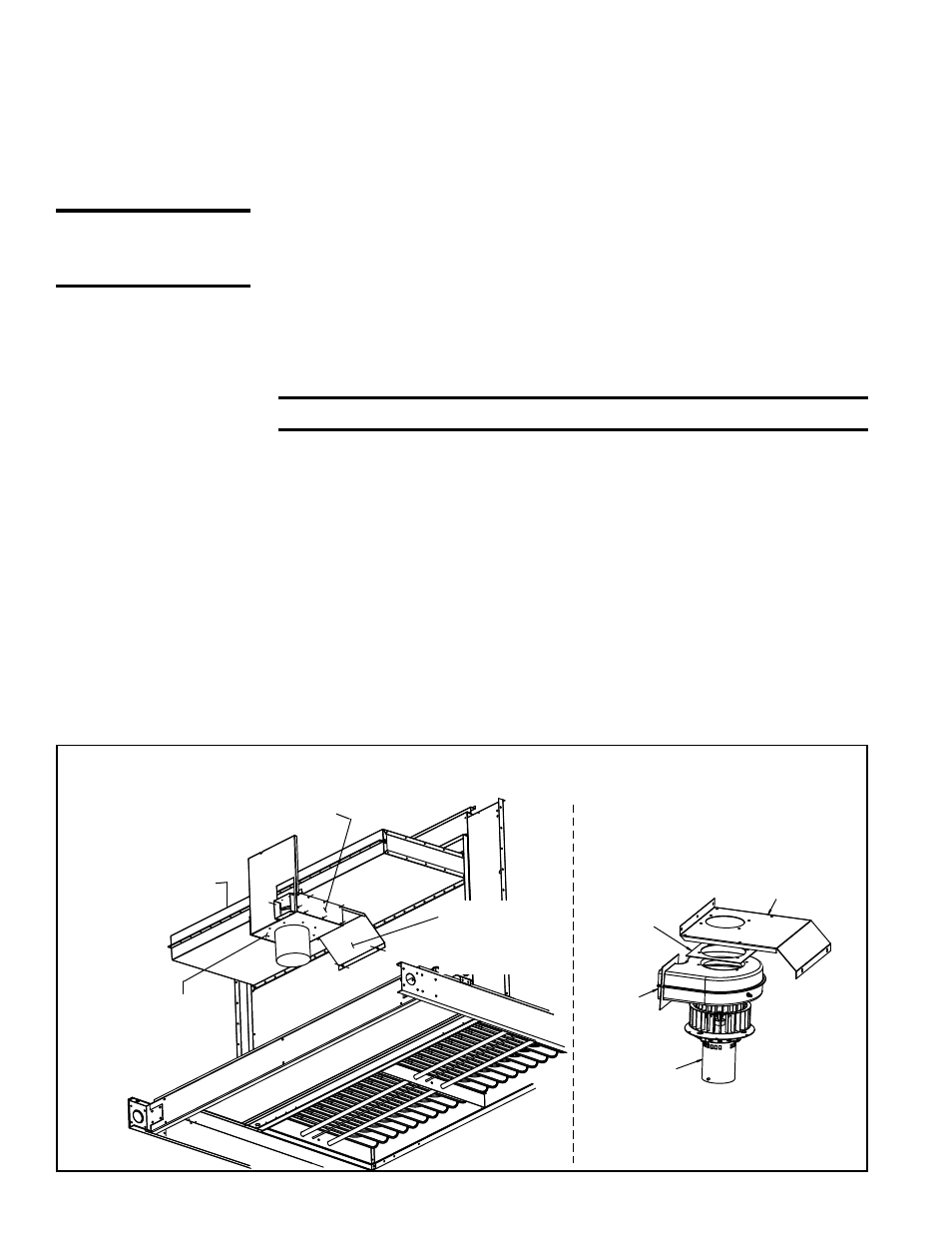
Venter Motor
and Wheel
Assembly
Venter Side Supports
Venter
Housing
and Support
Flue Collection
Box Assembly
Venter Support
Venter
Housing
Venter
Housing
Gasket
Motor and
Wheel Assy
OR, depending on the Cabinet size
and date of manufacture, venter
components may look more like
the one shown below.
FIGURE 10 - Heat Section (panels removed) showing Venter Assembly and Flue
Collection Box
4.0 Gas Heat Section Maintenance - RDCB, RDDC, RDDB and RDDC (cont'd)
4.1 Heat Exchanger, Burner, and Venter Maintenance (cont'd)