3 gas train – Reznor MAPS - A,B,C Users Manual User Manual
Page 26
Form O-MAPSIII&IV Cabinets A/B/C, Page 26
1) Call for Heat - The IQ controller calls for heat (there is a closure between "R" and
"W" and at least 2 VDC to the analog input). The ignition system circuit board will check
the modulating valve position and move to lightoff position. It checks to see that the
limit switch is closed and the pressure switch is open. If the pressure switch is closed,
the circuit board will wait indefinitely for the switch to open. If the switch is open, the
circuit board proceeds to prepurge.
2) Prepurge - After the actuator moves to its lightoff position, the circuit board ener-
gizes the venter motor and waits for the pressure switch to close. If the pressure switch
does not close at the beginning of a heat cycle, the venter motor will run for two min-
utes, then cycle off for 30 seconds, then on for two minutes, and so forth indefinitely.
When the pressure switch is proven closed, the venter motor ramps up to the appropri-
ate lightoff speed and the circuit board begins the prepurge time. If flame is present any
time while in prepurge, the prepurge time is restarted. If flame is present long enough
to cause lockout, refer to the Troubleshooting Guide in Paragraph 7.3.2. The ignition
system circuit board runs the venter motor for a 30-second prepurge time, then pro-
ceeds to the ignition trial period.
3) Ignition Trial Period - The ignition system circuit board energizes the spark and
main gas valve. The venter remains energized. If flame is sensed during the first 6
seconds, the spark is de-energized. If flame has not been sensed during the first 6 sec-
onds, the control de-energizes the spark output and keeps the gas valve energized for
an additional one second flame proving period. If flame is not present after the flame
proving period, the control de-energizes the gas valve and proceeds with three ignition
re-tries as specified in “Abnormal Heat Cycle, Ignition Retry”. If flame is present, the
circuit board proceeds to steady heat. After three re-tries, the board will lockout for one
hour. It will require a cycling of power to reset before the one-hour limit.
4) Modulating Heat - As long as the call for heat exists, the circuit board not only
modulates the gas to precisely meet varying load conditions, but also modulates the
combustion air to maintain stable performance and optimize thermal efficiency across
the entire modulating range. Circuit board inputs are continuously monitored to ensure
limit switch is closed and flame is established. When the call for heat is removed, the
ignition system circuit board de-energizes the gas valve and begins postpurge timing.
5) Post Purge - The venter motor output remains on for a 45 second postpurge period
after the system controller is satisfied.
Modulating Gas Control Sequence of Operation
4.3 Gas Train
4.2 Heat Section
Controls
(cont'd)
4.2.2 Ignition System
for Modulating Gas
Control (cont'd)
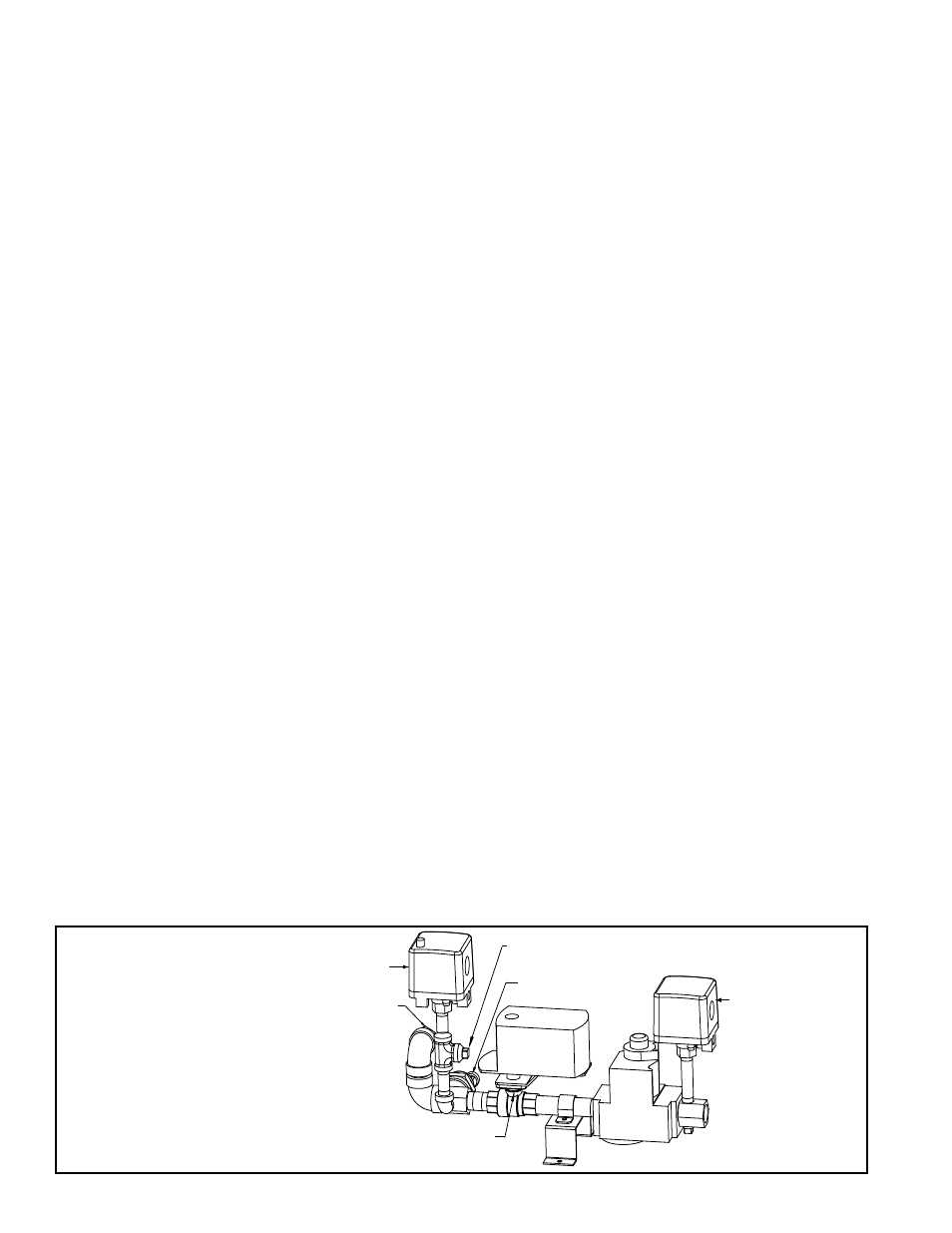
Location: The gas train is visible with the heat section door open.
Service: Carefully remove external dirt from the valves and check the wiring connec-
tions. Annually, in preparation for the heating season, check the single-stage operating
valve to be sure that it shuts gas flow off completely.
If any gas valves or other gas train components need to be replaced, they must be
replaced with identical part or factory-authorized replacement.
See component
identification in
FIGURE 15A, 15B, or
15C.
Orifice
Adapter
Ball Valve
Optional High Gas
Pressure Switch
Transducer
Ball Valve
Actuator
Gas
Valve
Optional Low Gas
Pressure Switch
Manifold Pressure Tap
FIGURE 15A -
Components in the
Heat Section Gas
Train - MAPS
®
III&IV
Cabinet A (Heat
Section Sizes 100,
150, 200)
4.0 Gas Heat
Section
Maintenance
(cont'd)