Reznor MAPS - A,B,C Users Manual User Manual
Page 38
Form O-MAPSIII&IV Cabinets A/B/C, Page 38
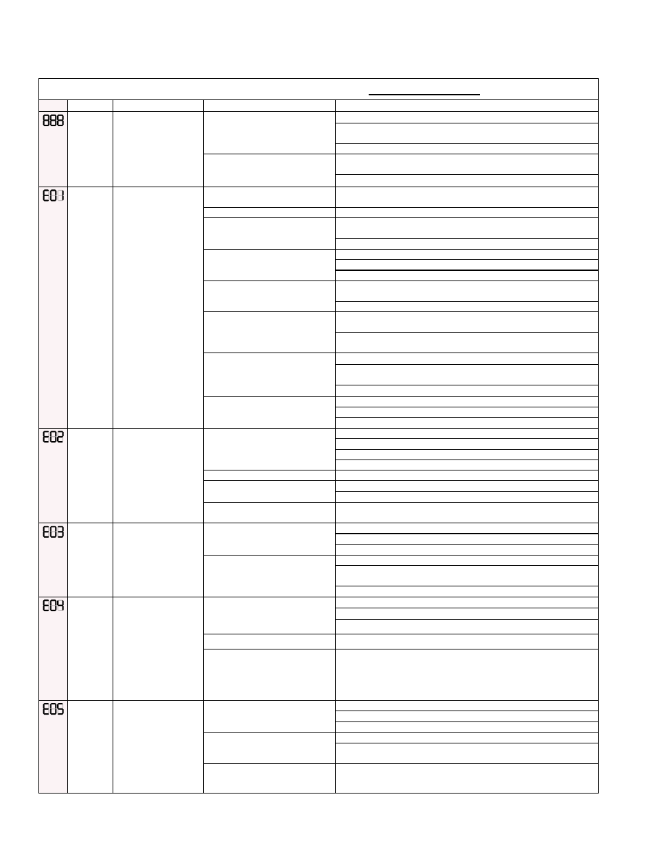
Gas Heat Section Modulating Control LOCKOUT ERRORS
Code
Alert
Description
Probable Causes
Solutions
Ignition
Board
Failure
(888)
Ignition board start-up
checks have detected
an error.
A. Faulty transformer
1. Check 24-volt transformer for correct output.
2. Check connections and wiring to control board and other
components connected to the 24 volt source.
3. Replace if necessary.
B. Faulty control board
1. Turn off power to the furnace, wait 30 seconds and turn power
back on. Re-try ignition sequence and see if the system responds.
2. Replace control board if necessary.
Failed
Ignition
(EO1)
Maximum
Retries (3)
Exceeded
The flame could
not be established
during multiple trial-
for-ignition periods
(3). The maximum
number of retries
has been exceeded
and the furnace is in
a lockout condition.
System Shutdown
alarm lockout will need
to be reset through
BacView interface or
IQ controller will need
to be power cycled.
A. Insufficient gas line pressure
1. Insure gas supply is connected to furnace and check for proper
line pressure.
B Gas valve control turned “OFF” 1. Turn gas valve to the “ON” position
C. No spark from direct spark
ignition
1. Check ignition voltage (115 VAC from board to transformer) and
wiring.
2. Check 24 VAC transformer for DSI board.
D. Insufficient intermediate gas
manifold pressure through gas
safety valve
1. Check for faulty gas valve wiring.
2. Check 24 VAC to gas valve assembly.
3. Check inlet pressure to safety gas valve.
D. (cont'd)
4. Check outlet pressure from the safety gas valve – adjust as
needed.
5. Replace safety gas valve if faulty.
E. Insufficient gas manifold
pressure to burner through
modulating ball valve assembly
1. Check voltage to gas valve actuator. (7 – 10 VDC depending on
model)
2. Check alignment and setscrew connection between ball valve and
actuator (See procedure in Paragraph 4.3.).
F. Burners do not light
1. Check spark rod assembly for proper location, spark gap, etc.
2. Verify that the spacing between the burner body and the burner
shield is equal across the entire length of the burner.
3. Check burner orifice for proper size and blockage.
G. Burners light and remain lit for
about 5 seconds
1. Check flame rod wiring and connections.
2. Check for proper alignment of flame rod.
3. Clean flame rod sensor.
Primary
Limit /
Fuse
Failure
(EO2)
The control board
safety fuse has
blown or the primary
temperature limit has
opened indicating
safe operating
temperatures for this
furnace have been
exceeded.
A. Improper circulating airflow
1. Check filter / replace if dirty.
2. Check for improperly sized duct system.
3. Check for faulty blower motor.
4. Check for faulty blower motor wiring.
B. Primary limit switch failure
1. Check for an open primary limit switch at ambient temperature.
C. Fuse is blown
1. Check and replace fuse on the board.
2. Make sure fuse socket is tight, crimp fuse terminals if necessary.
D. Faulty primary limit switch
wiring
1. Check primary limit wiring continuity from the switch to the control
board.
Modulation
Valve
Failure
(EO3)
The control lost the
position feedback from
the modulating gas
valve actuator.
A. Faulty modulation valve
actuator wiring
1. Ensure wiring is connected per unit wiring diagram.
2. Check for loose pins or bad connections.
3. Check for frayed wiring or shorts to ground.
B. Modulation valve actuator
failure
1. Ensure actuator has 24 V power.
2. Ensure actuator is receiving signal from the control board (2-10
VDC).
3. Check for actuator feedback to the control board (2-10 VDC)
Air Sensor
Failure
(EO4)
Pressure
Sensor
Reading
Low
The air sensor reading
is too low for operating
conditions or the air
pressure switch closed
when the sensor
indicates low flow
The pressure switch
MUST be open prior to
venter activation.
A. Faulty wiring or connections
1. Check pressure switch wiring.
2. Check inducer wiring.
3. Check for plugged or disconnected vacuum hoses.
B. Faulty pressure switch
1. Replace pressure switch.
C. Faulty pressure sensor,
located on the board
1. Replace board.
Air Sensor
Failure
(EO5)
Pressure
Sensor
Reading
High
The air sensor reading
is too high when the
venter is off or the
air pressure switch
open when the sensor
indicates high flow.
The pressure switch
MUST close to initiate
an ignition sequence.
A. Faulty wiring or hose
connections
1. Check pressure switch wiring.
2. Check venter motor wiring.
3. Check for broken or disconnected vacuum hoses.
B. Blocked or improper venting
1. Check air inlet and outlet for blockage.
2. Check venting configuration for excessive venting length,
improper sizing, etc.
C. Faulty pressure switch
1. Replace pressure switch.
7.3 Troubleshooting the Heat Section (cont'd)
7.3.3 Modulating Control Module on Cabinet A, B, C Gas Heat Sections (cont'd)