0 maintenance and service procedures (cont'd) – Reznor MAPS - A,B,C Users Manual User Manual
Page 10
Form O-MAPSIII&IV Cabinets A/B/C, Page 10
R-410A Refrigerant
R-410A Refrigerant
R-410A Refrigerant
R-410A Refrigerant
R-410A Refrigerant
Pressure Temperature
Pressure Temperature
Pressure Temperature
Pressure Temperature Pressure Temperature
PSI
°F
°C
PSI
°F
°C
PSI
°F
°C
PSI
°F
°C
PSI
°F
°C
1.8
-55 -48.3
49.5
1
-17.2
77.0
19
-7.2
112.2
37
2.8
218.2
75
23.9
4.3
-50 -45.6
50.9
2
-16.7
78.7
20
-6.7
114.4
38
3.3
235.9
80
26.7
7.0
-45 -42.8
52.2
3
-16.1
80.5
21
-6.1
116.7
39
3.9
254.6
85
29.4
10.1
-40 -40.0
53.6
4
-15.6
82.3
22
-5.6
118.9
40
4.4
274.3
90
32.2
13.5
-35 -37.2
55.0
5
-15.0
84.1
23
-5.0
121.2
41
5.0
295.0
95
35.0
17.2
-30 -34.4
56.4
6
-14.4
85.9
24
-4.4
123.6
42
5.6
316.9
100 37.8
21.4
-25 -31.7
57.9
7
-13.9
87.8
25
-3.9
125.9
43
6.1
339.9
105 40.6
25.9
-20 -28.9
59.3
8
-13.3
89.7
26
-3.3
128.3
44
6.7
364.1
110 43.3
27.8
-18 -27.8
60.8
9
-12.8
91.6
27
-2.8
130.7
45
7.2
389.6
115 46.1
29.7
-16 -26.7
62.3
10 -12.2
93.5
28
-2.2
133.2
46
7.8
416.4
120 48.9
31.8
-14 -25.6
63.9
11
-11.7
95.5
29
-1.7
135.6
47
8.3
444.5
125 51.7
33.9
-12 -24.4
65.4
12
-11.1
97.5
30
-1.1
138.2
48
8.9
474.0
130 54.4
36.1
-10 -23.3
67.0
13 -10.6
99.5
31
-0.6
140.7
49
9.4
505.0
135 57.2
38.4
-8
-22.2
68.6
14 -10.0
101.6
32
0.0
143.3
50
10.0
537.6
140 60.0
40.7
-6
-21.1
70.2
15
-9.4
103.6
33
0.6
156.6
55
12.8
571.7
145 62.8
43.1
-4
-20.0
71.9
16
-8.9
105.7
34
1.1
170.7
60
15.6
607.6
150 65.6
45.6
-2
-18.9
73.5
17
-8.3
107.9
35
1.7
185.7
65
18.3
645.2
155 68.3
48.2
0
-17.8
75.2
18
-7.8
110.0
36
2.2
201.5
70
21.1
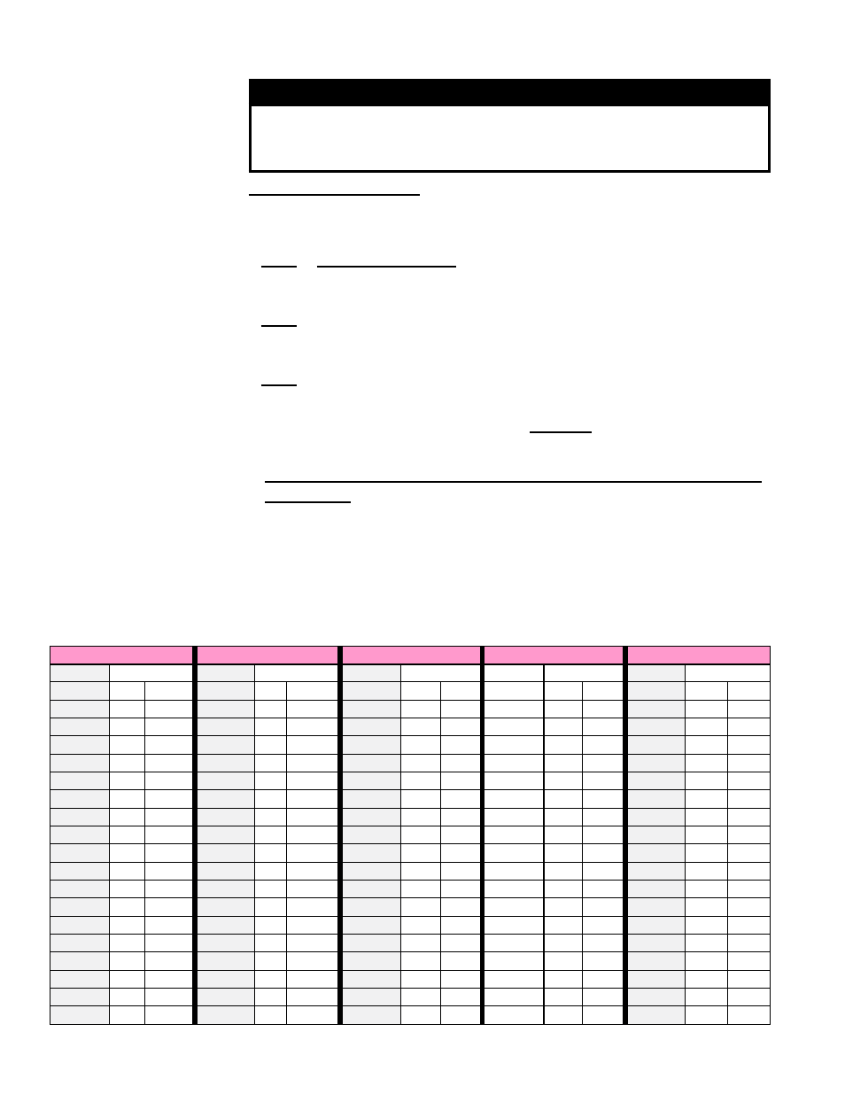
3.0 Maintenance and Service Procedures (cont'd)
3.5 Check
Refrigerant
Pressure and
Temperatures
(cont'd)
Temperature/Pressure Conversion Chart
WARNING
Do not release refrigerant to the atmosphere. When adding or
removing refrigerant, the qualified technician must comply
with all national, state/province, and local laws.
Determine SUPERHEAT
Measure and record temperature (insulate probe from surrounding air temperature)
and pressure in the suction line at the compressor inlet.
STEP 1) Record Measurements: Temperature = _______°F (°C) and
Pressure = _______ psig
STEP 2) From Temperature/Pressure Conversion Chart (below), convert
Measured Pressure (STEP 1) to ________°F (°C)
STEP 3) Subtract Measured Temperature (STEP 1) from Temperature from
Conversion Table (STEP 2)
________°F (°C) - ________°F (°C) = ________°F (°C) degrees of
Superheat
Recommended superheat range is 8 to 12 degrees F (4.5 to 6.7
degrees C).
Typically, too much superheat indicates that the evaporator coil is undercharged.
Too little superheat typically indicates that the evaporator coil is overcharged and
may potentially flood liquid refrigerant to the compressor. To reduce the superheat,
adjust the thermal expansion valve by turning the adjusting stem counterclock-
wise. To increase the superheat, adjust the thermal expansion valve by turning the
adjusting stem clockwise.