0 energy recovery module, Option er1, 0 energy recovery module, option er1 – Reznor MAPS - A,B,C Users Manual User Manual
Page 31
Form O-MAPSIII&IV Cabinets A/B/C, P/N 257004R8, Page 31
Electric Heating
Elements and
Controls
Service: Check the heating elements at the beginning of the heating season. The ele-
ments are assembled and attached to the electrical panel that is visible on the inner
side of the electric heat section. Slide the panel out to access the elements. Carefully
clean all dust and dirt from the heating elements using a brush or steel wool. With a
vacuum or air hose, clean the inside of the cabinet especially the bottom and sides
where dirt and dust will accumulate.
If a replacement is needed, order a complete heat section assembly.
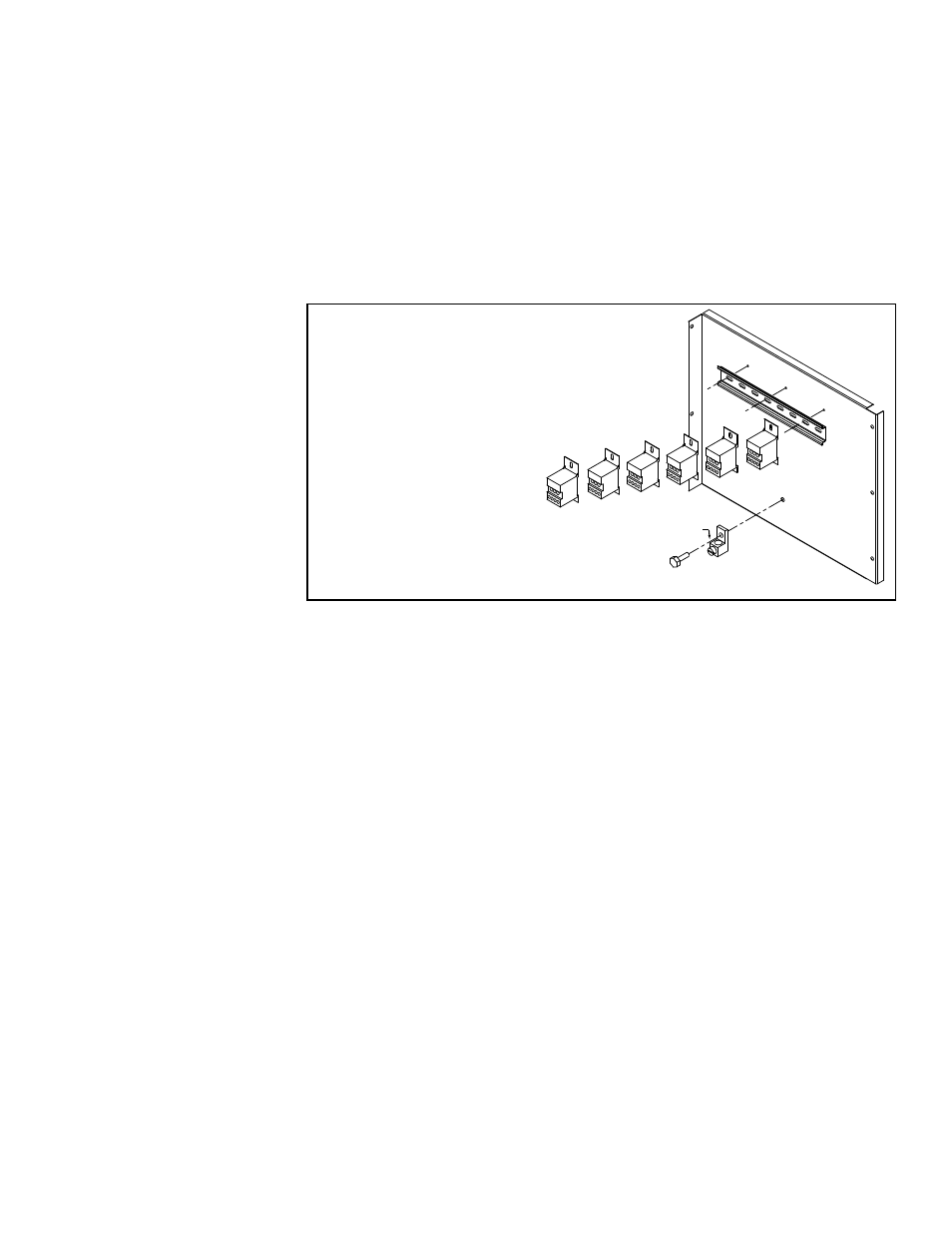
High Voltage Panel in Electric Heat Section
Grounding Lug
Distributor Blocks
are on this panel.
(qty varies by size
and voltage)
Location: See the control location illustration in FIGURE 1, page 5, and FIGURE 18,
below, the additional high voltage panel in the electric heat section. Quantities and
types of distribution blocks, fuses, and contactors depend on the size of the unit.
If replacement parts are required, check with your distributor and use only factory-
authorized replacements.
FIGURE 18 - High
Voltage Panel in the
Electric Heat Section
- Models RECB,
RECC, REDB, and
REDC
6.0 Energy
Recovery
Module,
Option ER1
If the MAPS
®
unit is equipped with an optional energy recovery module (Option ER1A,
ER1B, or ER1C), there are additional maintenance and service procedures unique to
the energy recovery wheel.
Refer to the energy recovery module manual, Form I-MAPSIII&IV-ER, for required
maintenance instructions and service information.