Reznor MAPS - A,B,C Users Manual User Manual
Page 29
Form O-MAPSIII&IV Cabinets A/B/C, P/N 257004R8, Page 29
Gas Manifold
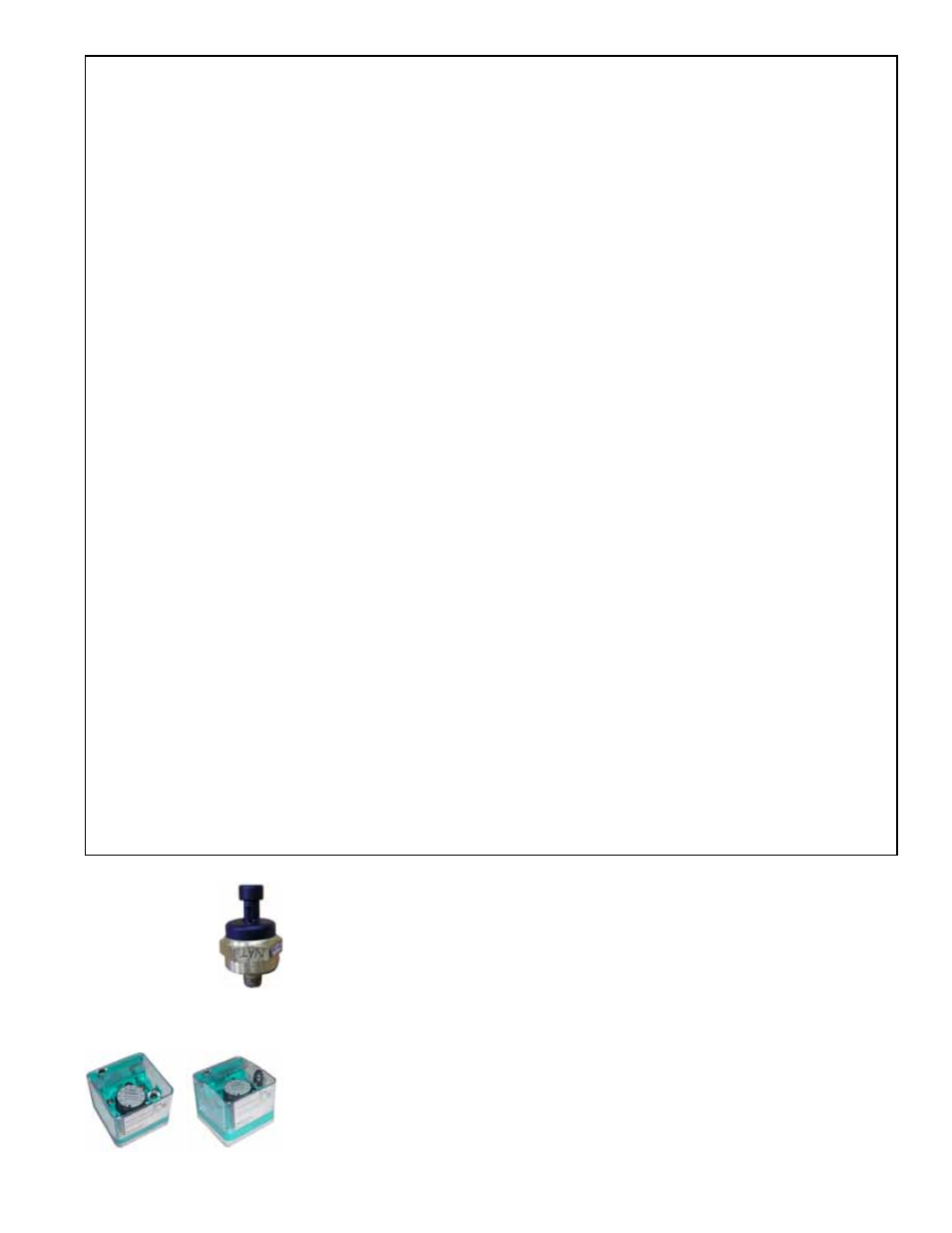
Transducer
Location: See FIGURE 15.
Function: The transducer reads the manifold pressure and sets the venter motor
speed to precisely match the designed combustion settings.
Service: If the transducer needs to be replaced, use only a factory-authorized replace-
ment part designed for the purpose.
a) Scroll down to Menus and press Enter.
b) Enter password (0000) using the INC button and the right arrow button and press Enter.
c) Scroll down to the Service Menu and press Enter.
d) Scroll down to Test Mode and press Enter.
e) Scroll down to Manual Test; press Enter; press the INC button to change the command from OFF to ON; and
press
Enter.
f) After the system has completed the shutdown sequence, connect the gas manometer to the manifold pressure
tap next to the transducer (See
FIGURE 15 and illustration below).
g) On the display, scroll down to Heat Stg 1 and press Enter.
h) Scroll down to ModHeat which has a default setting of 100%.
2.
With the
ModHeat set at 100%, measure the manifold pressure. If the manifold pressure matches the High
Setting value in the chart (page 28), continue to Step No. 3. If the manifold pressure does not match the value
in the chart and the ball valve is fully or close to fully open, adjust the pressure screw(s) on the Honeywell
valve (See
FIGURE 16) until the pressure matches the chart. Note, if the manifold has a dual valve, adjust both
pressure screws so that they are the same. When the manifold pressure measured at the manometer matches
the pressure listed in the chart, make a note for future reference of the position of the ball valve stem in relation
to the dash marks on the actuator.
3.
On the display, change the
ModHeat setting to 0% modulation and allow the ball valve to go to its lowest setting.
Check the manifold pressure on the manometer. If the manifold pressure matches the Low Setting value in the
chart, skip to Step No. 4. If the manifold pressure does not match the low (0%) value on the chart, the ball valve
will need to be adjusted. Follow these steps:
a) While the unit is still firing at 0% modulation, remove the ball valve actuator. To do this, locate the screw on the
rear of the actuator and remove it. Loosen the actuator set screw (See
FIGURE 17B), and carefully remove
the actuator by lifting it straight up. Do not disconnect any wires.
b) Using adjustable pliers, slowly turn the ball valve stem until the manifold pressure on the manometer matches
the low setting on the chart.
Important NOTE: If the valve is adjusted too far closed and the flame goes out, let the unit recycle and then
manually open the ball valve to the 100% open position noted in Step No. 2. When the unit is firing at full fire,
re-attach the actuator to the ball valve, and repeat the procedure beginning with Step No. 2.
c) When the manometer readings match the values in the chart and before re-installing the actuator, the burr
left on the ball valve stem from the previous set screw setting needs to be removed. Either lightly file the burr
on the valve stem to prevent the set screw from returning to the previous position or remove the valve stem,
rotate it 180° so that the set screw contacts the opposite side of the stem, and re-install the valve stem.
d) Re-install the actuator making sure it is level on the ball valve mounting plate.
e) Re-check the setting by going to full fire (Set ModHeat at 100%) and returning to 0% modulation (Set
ModHeat at 0%). Measure the manifold pressure. The adjusted gas pressure should be close to the value in
the chart on page 28. If not, repeat the procedure.
4.
When the settings are in agreement with the chart and testing is complete, remove the manometer. Set
ModHeat
to 100%. Scroll the display back to
Test Mode and press Enter. Disable Test Mode by pressing the INC button
to change the command
from ON to OFF; and press Enter.
Optional Gas
Pressure Switches
Location: Low pressure switch is at the entrance to the gas train. The high pressure
switch is at the burner end. See
FIGURE 15.
Function: Monitors gas pressure and shuts down the heat section if gas pressure
becomes too low or too high. The low pressure switch is an auto reset type and is set
at 50% of the maximum manifold pressure. The high pressure switch requires manual
reset and is set at 125% of manifold pressure.
Service: There are no replaceable parts and the settings are non-adjustable. If replace-
ment is required, use identical factory-authorized safety switches.