3 gas train (cont'd) – Reznor MAPS - A,B,C Users Manual User Manual
Page 28
Form O-MAPSIII&IV Cabinets A/B/C, Page 28
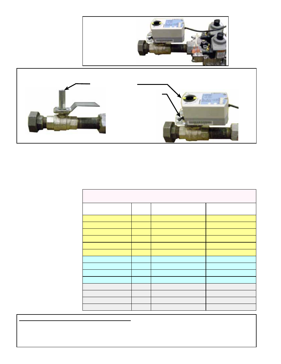
Ball Valve with actuator removed
Ball Valve Actuator
Modulates the Gas Flow
Actuator
Set Screw
(shown on the
right or closed
position)
Ball Valve Shaft
FIGURE 17B - Ball Valve with Actuator in Modulating Gas Control (Option AG70) Manifold
Modulating System
Gas Valve (Ball
Valve and Actuator)
Adjustment
4.3 Gas Train
(cont'd)
Inspect the position of the ball valve shaft.
□
In the fully open position, the dash marks on the top of the shaft should be aligned
with the gas piping.
□
In the fully closed position, the dash marks on the top of the shaft should be
aligned at a 90° angle across the gas piping.
If the ball valve shaft is not properly aligned or if the manifold pressure does not match
the settings in the chart below, the ball valve will need to be adjusted.
FIGURE 17A -
Ball Valve and
Actuator in Gas
Control Option
AG70
Manifold Pressures
for MAPS
®
III&IV Gas
Modulation System
Manifold Pressure (" w.c.) Measured
at the Pressure Tap by the Gas Transducer
Cabinet and Heat
Section Size
Gas
Type
High Setting
100% on ModHeat
Low Setting
0% on ModHeat
A-Cab 100
Nat
3.4" w.c.
0.15" w.c.
A-Cab 150
Nat
3.4" w.c.
0.15" w.c.
A-Cab 200
Nat
3.4" w.c.
0.15" w.c.
A-Cab 100
LP
10.0" w.c.
0.5" w.c.
A-Cab 150
LP
10.0" w.c.
0.5" w.c.
A-Cab 200
LP
10.0" w.c.
0.5" w.c.
B-Cab 250
Nat
3.4" w.c.
0.15" w.c.
B-Cab 300
Nat
3.4" w.c.
0.15" w.c.
B-Cab 250
LP
10.0" w.c.
0.45" w.c.
B-Cab 300
LP
10.0" w.c.
0.45" w.c.
C-Cab 400
Nat
3.4" w.c.
0.2" w.c.
C-Cab 500
Nat
3.4" w.c.
0.2" w.c.
C-Cab 600
Nat
3.4" w.c.
0.2" w.c.
C-Cab 700
Nat
3.4" w.c.
0.2" w.c.
To adjust gas modulation follow instructions below:
1. Checking modulation requires a manometer capable of reading to 0.10" w.c. Connect the manometer as
instructed in Step 1.f) below.
To check and adjust the modulation system, the IQ controller must be in
Test Mode. On the control display in the
electrical compartment, follow the steps below to enter
Test Mode.
4.0 Gas Heat
Section
Maintenance
(cont'd)