0 general – Reznor MAPS - A,B,C Users Manual User Manual
Page 2
Form O-MAPSIII&IV Cabinets A/B/C, Page 2
1.0 General
This booklet includes operation, maintenance, and service information for Cabinet
Sizes A, B, and C of the MAPS
®
III and MAPS
®
IV Models listed below. Before begin-
ning any procedure, carefully review the information, paying particular attention to the
warnings. Handling of refrigerant should only be performed by a certified HVAC techni-
cian with knowledge of the requirements of R-410A refrigerant and in compliance with
all codes and requirements of authorities having jurisdiction.
The instructions in this manual apply to the following MAPS
®
Models in Cabinet A, B,
and C Sizes and Model JHUP 250 and 300 duct furnace curb option.
1.0 General ....................................................2-3
2.0 Maintenance Requirements ..................3-6
2.1 Maintenance Schedule.....................................4
2.2 Control Locations .............................................5
2.3 Cross-Reference of Models and
Cabinet Sizes A, B, and C ..............................6
3.0 Maintenance & Service Procedures ...6-21
3.1 Filters ..............................................................6
3.2 Drive Components ...........................................7
3.3 Condenser Fans...............................................8
3.4 Coil Maintenance .............................................8
3.5 Check Refrigerant Pressure & Temperatures
(subcooling and superheat) .............................9
3.6 Compressor Operation, Maintenance, and
Replacement.................................................. 11
3.7 Thermostatic Expansion Valves .....................19
3.9 Other Controls ................................................20
3.8 Optional Dampers and Damper Controls .......20
4.0 Gas Heat Section Maintenance -
RDCB, RDCC, RDDB, RDDC .............21-30
4.1 Heat Exchanger, Burner, and Venter..............21
4.2 Heat Section Controls ....................................25
4.3 Gas Train........................................................26
4.4 Other Gas Heat Section Controls / Sensors ..30
5.0 Electric Heat Section Maintenance -
RECB, RECC, REDB, REDC ..............30-31
Option ER1 ..............................................31
7.0 Troubleshooting .................................32-39
7.1 Troubleshooting - Refrigeration (All Models) ..32
7.2 Compressor Digital Controller
7.3 Troubleshooting the Heat Section .................34
INDEX .............................................................40
Table of Contents
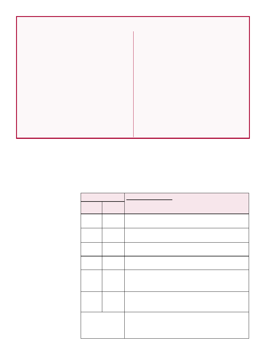
Model
System Description (MAPS
®
III models have
staged cooling; MAPS
®
IV models have modulating
cooling.)
MAPS
®
III MAPS
®
IV
RCB
RCC
Makeup Air Cooling Packaged System, 1500-9000
CFM
RDCB RDCC Makeup Air Cooling Packaged System, 1500-9000
CFM, with Gas Heat Section (100-700 MBH)
RECB
RECC Makeup Air Cooling Packaged System, 1500-9000
CFM, with Electric Heat Section (10- 88 kw)
RDB
RDC
Makeup Air Cooling and Re-heat Pump Reheat Cycle
Packaged System, 1500-9000 CFM
RDDB
RDDC
Makeup Air Cooling and Re-heat Pump Reheat Cycle
Packaged System, 1500-9000 CFM, with a Gas Heat
Section (100-700 MBH)
REDB
REDC
Makeup Air Cooling and Re-heat Pump Reheat Cycle
Packaged System, 1500-9000 CFM, with Electric Heat
Section (10 - 88 kw)
JHUP
Optional Curb Section with 250 or 300 MBH Gas-Fired
Duct Furnace installed with a Model RDCB, RDCC,
RDDB or RDDC with a Size 250 or 700 Heat Section to
provide 500 or 1000 MBH heating
NOTE: To confirm that this
booklet is applicable, see
list of Model and Cabinet
Sizes in Paragraph 2.3,
page 6.