2 compressor digital controller, Troubleshooting - all maps, Iv models – Reznor MAPS - A,B,C Users Manual User Manual
Page 33: Compressor digital controller led’s
Form O-MAPSIII&IV Cabinets A/B/C, P/N 257004R8, Page 33
H. High discharge
pressure.
1. Refrigerant overcharge
1. Check subcooling. (Paragraph 3.5) Adjust refrigerant charge.
2. Thermal expansion valve setting
2. Check superheat and adjust valve as needed
.
2. Air inlet to condenser dirty or obstructed.
3. Check for proper clearances and possible air recirculating.
4. Condenser fan motor defective.
4. Check condenser fan motor(s).
I. Suction
pressure is too
low.
1. Refrigerant undercharge.
1. Check subcooling. (Paragraph 3.5) Add refrigerant as needed.
2. Thermal expansion valve setting
2. Check superheat and adjust valve as needed.
3. Blower running backward.
3. Interchange any two wires from 3 phase disconnect.
4. Loose blower, pulley, or belts.
4. Check drive pulley alignment and belt tension.
5. Dirty filter.
5. Check filter and evaporator coil.
6. Too little air flow or low entering air temperature. 6. Check airflow and entering air wet bulb conditions.
7. Restriction in suction or liquid line.
7. Check refrigerant circuit for restriction.
J. Head pressure
too low.
1. Insufficient refrigerant charge.
1. Check subcooling (Paragraph 3.5). Check for leak. Repair and add refrigerant.
2. Defective or improperly adjusted expansion valve. 2. Check superheat (Paragraph 3.5) and adjust thermal expansion valve.
3. Low suction pressure.
3. See “I. Suction pressure too low” above.
4. Defective compressor.
4. See "G. High suction pressure” above.
K. Compressor
short cycles.
1. Improper refrigerant charge.
1. Check subcooling and superheat. (Paragraph 3.5)
2. Defective high or low pressure control.
2. Check high or low pressure switch.
3. Liquid floodback.
3. Possible tight bearings, see above.
4. Defective expansion valve.
4. Check superheat and thermal expansion valve.
5. Poor air distribution.
5. Check ductwork for recirculating.
6. High discharge pressure.
6. See “H. High discharge pressure” above.
7. Leaking discharge valves in compressor.
7. See “G. High suction pressure” above.
L. Running cycle
is too long or
unit operates
continuously.
1. Refrigeration undercharged.
1. Check subcooling (Paragraph 3.5) and add refrigerant.
2. Dirty filter or evaporator coil.
2. Check filter, coil, and airflow. Clean and/or replace.
3. Dirty or clogged condenser coil.
3. Check coil and airflow. Clean.
4. Air or other non-condensables in system.
4. Check equalized high side pressure with equivalent outdoor temperature.
5. Defective compressor.
5. See “G. High suction pressure” above.
6. Restriction in suction and liquid line.
6. Check for restrictions in refrigerant circuit.
7. Control contacts stuck.
7. Check wiring.
M. Supply air
temperature is
too high.
1. Refrigerant undercharge or leak in system.
1. Check subcooling
(Paragraph 3.5). Check for leak. Repair and add refrigerant.
2. Evaporator plugged with dirt or ice.
2. Check evaporator, airflow, and filter. Clean.
3. Improperly adjusted or defective expansion valve. 3. Check superheat (Paragraph 3.5) and adjust thermal expansion valve. Check
expansion valve bulb placement and insulation.
4. Defective compressor.
4. Check compressor for proper operation.
5. High discharge pressure.
5. See “H. High discharge pressure” above.
6. Airflow is too high.
6. Check external static pressure.
N. Supply air
temperature is
too low.
1. Airflow is too low.
1. Check evaporator coil; check filters; check for closed dampers or grills; check
drive for loose parts, belts, or misalignment; and check external static pressure.
2. Return air temperature too low.
2. Check entering air wet bulb conditions.
O. Liquid line is
too hot.
1. Refrigerant undercharge.
1. Check subcooling.
2. High discharge pressure.
2. See H. above.
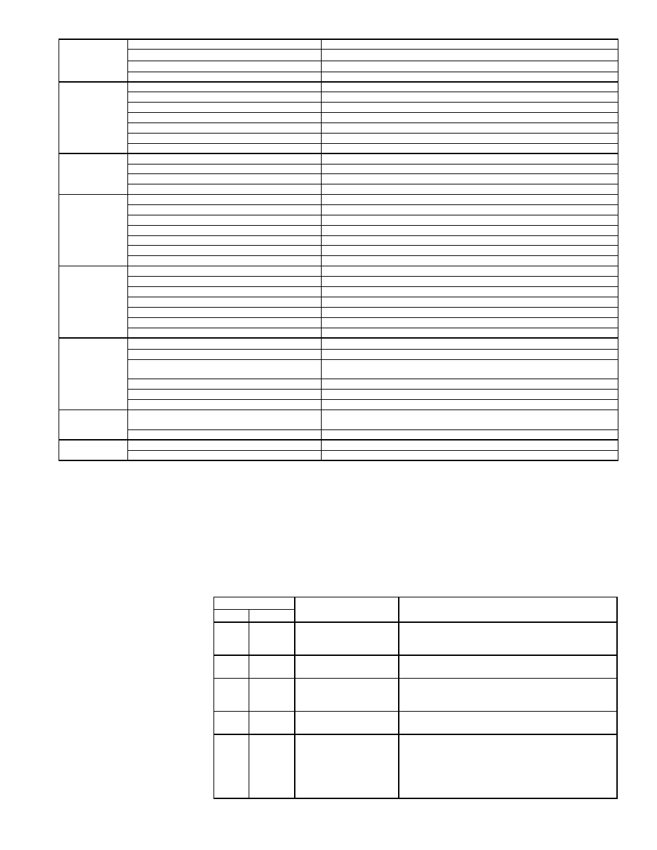
Compressor Digital Controller LED’s
LED State
Indicates
Additional Information
Color
CODE
Green Solid
Power (24VAC present at
power terminals)
Modulating capacity compressor starts only when
demand signal input is above 1.45 VDC and no
ALERTS (red LED flashes) are active.
Green. Flashing
Anti-short cycle timer is
active
Yellow Solid
Unloader (Solenoid valve
is energized; compressor
capacity is 0.)
Modulating capacity compressor always unloads for 0.1
second at startup.
Red
Not lit
No abnormal operation
alerts
Red
2 Flashes High Discharge
Temperature Alert
(thermistor temperature
above 268°F or
thermistor is short
circuited)
Modulating capacity compressor will be allowed to
restart after a 30-minute delay and after the thermistor
temperature is below 250°F. Compressor will lockout
after 5 alerts within 4 hours and can only be reset by
cycling the 24VAC power off and on.
7.2 Compressor
Digital
Controller
Troubleshooting
- all MAPS
®
IV
Models
General - The digital controller is located in the electrical compartment and acts as the
interface between the digital compressor and the unit controller. If the unit interface dis-
play indicates critical Alarm Code 17, Modulating Capacity Compressor Failure, check
the LED lights on the digital controller.
The alert code (red LED flashes) on the digital controller remains active and the com-
pressor de-energized until the reset conditions have been met or the 24VAC power
is cycled off and on. All Codes except 6 result in compressor (contactor and unloader
valve) being de-energized.
(continued)
NOTE: To identify MAPS
®
IV
Models, see Paragraph 1.0.