Ad b c, 0 maintenance/service procedures (cont'd), 4 coil maintenance (cont'd) – Reznor MAPS III, Cabinet D RECB Users Manual User Manual
Page 8: Ab d c, Condenser coils by circuit
Form O-MAPSIII Cabinet D, P/N 222918R9, Page 8
3.0 Maintenance/Service Procedures (cont'd)
A
D
B
C
15 ton MC Coil
15 ton MC Coil
15 ton
MC Coil
15 ton
MC Coil
Discharge Line Ø 0.875
Discharge Line Ø 0.875
Discharge Line Ø 0.875
Discharge Line Ø 0.875
Liquid Line
Ø 0.875
Liquid Line
Ø 0.875
Liquid Line Ø 0.875
Liquid Line Ø 0.875
Filter Drier
Filter Drier
Filter Drier
Filter Drier
Inlet 1
Ø 0.881
Inlet 2
Ø 0.881
Inlet 2
Ø 0.881
Inlet 1
Ø 0.881
Inlet 2
Ø 0.881
Inlet 1
Ø 0.881
Inlet 2
Ø 0.881
Inlet 1
Ø 0.881
Outlet
Ø 0.881
Outlet
Ø 0.881
Outlet
Ø 0.881
Outlet
Ø 0.881
(See compressor locations on page 12.)
Evaporator Coils by
Circuit (interlaced)
All four
outlets
Ø 1.380
A
B D
C
Suction Line Ø 1.375
Suction Line Ø 1.375
Suction Line Ø 1.375
Suction Line Ø 1.375
RCB/RDCB/RECB 720 and
RDB/RDDB/REDB 722, 804, and 842
(T
o TXV valves and Distributors
on Evaporator Coils)
Condenser Coils by Circuit
3.4 Coil Maintenance (cont'd)
Condenser Coils by Circuit
Condenser Coils by Circuit
A
D
A
B C
D
A
B
C
10 ton MC Coil
5 ton MC Coil
10 ton MC Coil
15 ton MC Coil
15 ton MC Coil
Inlet 1
Ø 0.881
Inlet 1
Ø 0.879
Inlet
Ø 0.881
Inlet 2
Ø 0.881
Inlet 2
Ø 0.879
Inlet 1
Ø 0.881
Inlet 2
Ø 0.881
Outlet
Ø 0.881
Outlet
Ø 0.881
Outlet
Ø 0.879
Outlet
Ø 0.881
Discharge Line Ø 0.875
Discharge Line Ø 0.875
Discharge Line Ø 0.875
Discharge Line Ø 0.500
Discharge Line Ø 0.875
Discharge Line Ø 0.875
Liquid Line Ø 0.875
Liquid Line
Ø 0.875
Liquid Line
Ø 0.875
Liquid Line
Ø 0.875
Liquid Line
Ø 0.500
Liquid Line Ø 0.875
Filter Drier
Filter Drier
Filter Drier
Filter Drier
Filter Drier
Filter Drier
A
D
B
C
Discharge Line Ø 0.875
Discharge Line Ø 0.875
Discharge Line Ø 0.875
Discharge Line Ø 0.875
Liquid Line
Ø 0.875
Liquid Line
Ø 0.875
Liquid Line Ø 0.875
Liquid Line Ø 0.875
Filter Drier
Filter Drier
Filter Drier
Filter Drier
Outlet
Ø 0.881
Outlet
Ø 0.881
Outlet
Ø 0.881
Outlet
Ø 0.881
Inlet
Ø 0.881
Inlet 2
Ø 0.881
Inlet 1
Ø 0.881
Inlet 2
Ø 0.881
Inlet 1
Ø 0.881
Inlet
Ø 0.881
10 ton MC Coil
10 ton MC Coil
15 ton MC Coil
15 ton MC Coil
(See compressor locations on page 12.)
(See compressor locations on page 12.)
(See compressor
locations on page 12.)
Evaporator Coils by
Circuit (interlaced)
Evaporator Coils by
Circuit (interlaced)
A
C
D
A
C
D
A
C
D
All three
outlets
Ø 1.380
All four
outlets
Ø 1.380
Suction Line Ø 1.375
Suction Line Ø 1.375
Suction Line Ø 0.875
Suction Line Ø 1.375
Suction Line Ø 1.375
Suction Line Ø 1.375
RCB/RDCB/RECB 480 and
RDB/RDDB/REDB 538, 564, and 602
RCB/RDCB/RECB 360 and
RDB/RDDB/REDB 418, 444, and 484
RCB/RDCB/RECB 600 and
RDB/RDDB/REDB 658, 684, and 722
A
B D
C
Suction Line Ø 1.375
Suction Line Ø 1.375
Suction Line Ø 1.375
Suction Line Ø 1.375
(T
o TXV valves and Distributors on Evaporator Coils)
(T
o TXV valves and Distributors on Evaporator Coils)
(T
o TXV valves and Distributors
on Evaporator Coils)
Condenser Coils by Circuit
15 ton MC Coil
Inlet
Ø 0.506
Outlet Ø 0.506
Inlet
Ø 0.879
Outlet Ø 0.879
Outlet Ø1.380
Outlet Ø1.380
Outlet Ø 0.879
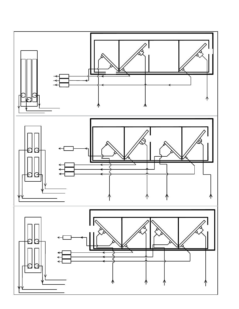
FIGURE 4 (cont'd) - Coil Circuits (Views are from the control side of the system.)