Reznor MAPS III, Cabinet D RECB Users Manual User Manual
Page 22
Form O-MAPSIII Cabinet D, P/N 222918R9, Page 22
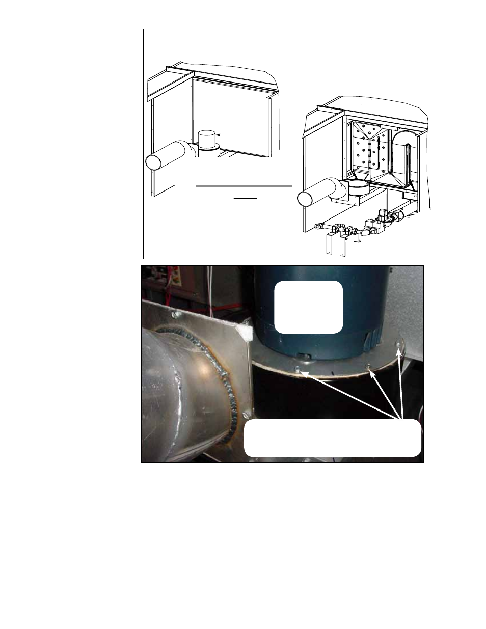
FIGURE 7 - View of the Heat Section showing Access to the
Heat Exchanger by Removing the Venter Assembly and the
Heat Exchanger Access Panel
View BEFORE Removing
Venter Assembly and
Heat Exchanger Access Panel
Venter
Assembly
Heat Exchanger
Access Panel
View AFTER Removing
Venter Assembly
and Heat Exchanger
Access Panel
NOTE: Some panels have been
removed for illustration clarity.
Gas T
rain and Burner -
See Paragraph 4.1.2 to
remove slide-out burner
.
b) Locate the screws shown in FIGURE 8. Remove the screws and carefully lift
the venter wheel out of the housing. Remove the whole motor and wheel assembly
including the large mounting plate.
NOTE:
To clean the venter assembly or replace parts, follow the instructions in
Paragraph 4.1.3.
5. With the venter motor and wheel assembly removed, the large heat exchanger
access panel is now removable (See
FIGURE 7). Disconnect the limit switch wires.
Remove the screws securing the heat exchanger access panel and remove the
panel.
6. The outside of the heat exchanger is now in view here and through the blower
door. Remove any external dirt or dust accumulation. Use a 60" inspection mirror
to view the heat exchanger sections. Check the heat exchanger for cracks or
holes. If a crack or hole is observed, replace the heat exchanger.
FIGURE 8 - Remove
the Venter Assembly
before Removing
the Heat Exchanger
Access Panel
Remove the perimeter sheetmetal
screws that secure the motor mount-
ing plate to the venter housing.
NOTE: To clean the
venter assembly while
it is removed, follow the
instructions in Paragraph
4.1.3.
Lift venter
assembly
out of the
housing.
4.1 Heat Exchanger,
Burner, & Venter
Maintenance
(cont'd)
4.0 Gas Heat
Section
Maintenance
(cont'd)