0 maintenance requirements (cont'd), 2 control locations – Reznor MAPS III, Cabinet D RECB Users Manual User Manual
Page 4
Form O-MAPSIII Cabinet D, P/N 222918R9, Page 4
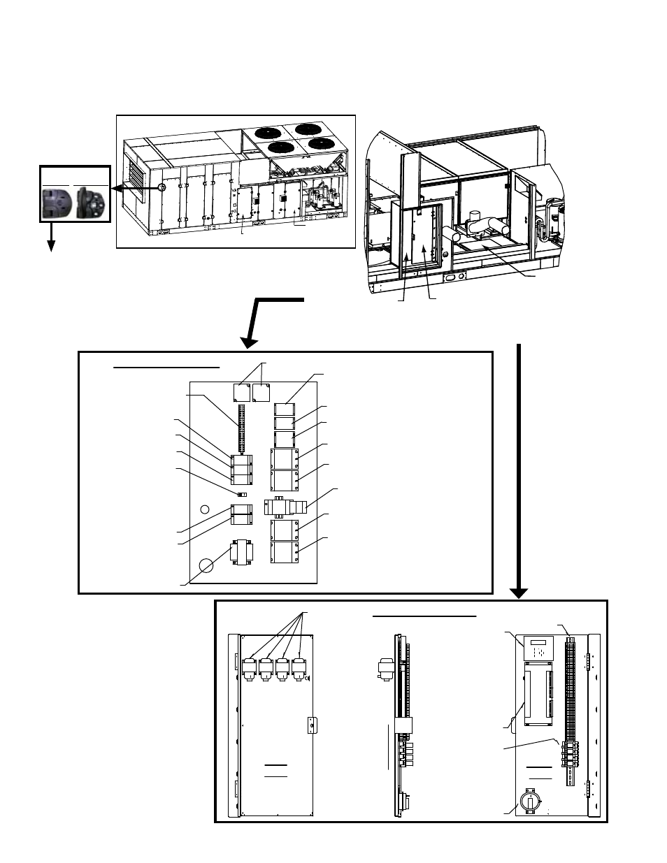
FIGURE 1 - Access Panels and High and Low Voltage Control Locations
2.0 Maintenance Requirements (cont'd)
2.2 Control Locations
High Voltage Panel
(behind low voltage
panel; post is removed
for less restricted view)
Low Voltage Panel
(hinged; swings out
to access rear side and
high voltage panel behind)
Gas Heat
Section
Control Panel
(See Para 4.2.1.)
High Voltage Panel
Control
Transformer
Distribution
Block
Distribution Block
Distribution Block
Distribution Block
Distribution Block
Grounding
Lug
Terminal Blocks
Phase Loss
Monitor
Contactor (Condenser
Fan B & C)
Contactor (Condenser Fan A & D)
Contactor (Reheat Compressor E)
Contactor (Compressor D)
Contactor (Compressor C)
Contactor (Compressor B)
Contactor (Compressor A)
Motor Starter
Rear
View
Side V
iew
Front
View
75VA
transformers
Optional Dirty
Filter Switch
Digital
Controller
Controller
Display
Wire Harness
Assembly
Optional
Relays
and Bases
Low Voltage Panel
Control Compartment
Access Door
Heater Controls
Access Door
Filter Access
Coil Access
Fan and Motor
Access
Condenser Section
A
B
C
D
Door Hinge
The filter, coil, and fan/motor cabinet
doors can be opened from the left or
right. On the side of the door to be
opened, unlock the two hinges with
an allen key. Pull out unlocked "fronts"
of hinges to 90 degrees to expose
handles needed to open the door.
Re-lock hinges when door is closed.
Locked Unlocked
NOTE: Electric heat
Models RECB and
REDB have additional
electrical panels in
the heat section; see
Paragraph 5.0, page
33.