0 maintenance procedures (cont'd), 9 other controls (cont'd), 5 hot gas bypass valve, option auc9 – Reznor MAPS III, Cabinet D RECB Users Manual User Manual
Page 20: 4 voltage protection, option pl4, Bypass valve 3.9.2 air proving switch
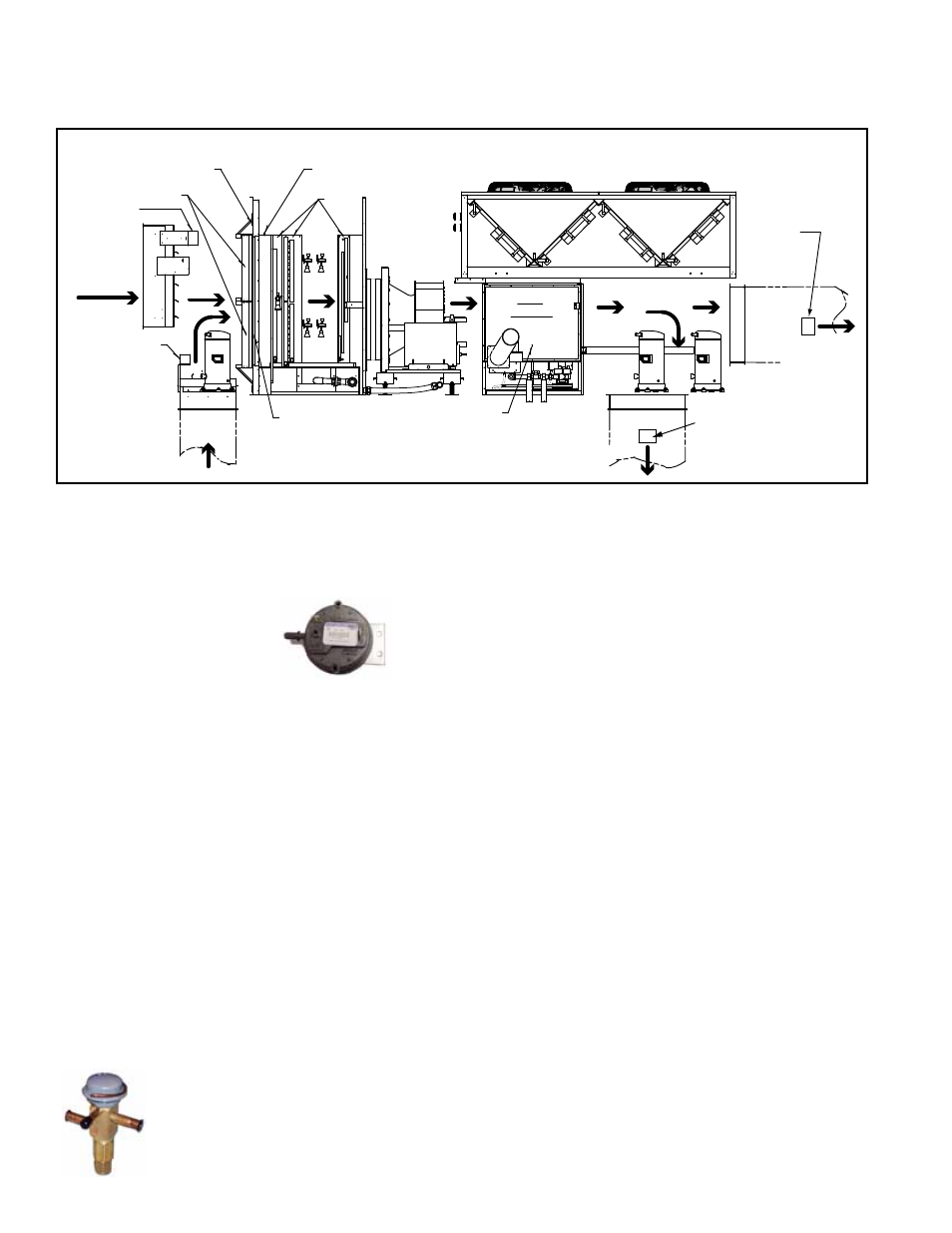
Form O-MAPSIII Cabinet D, P/N 222918R9, Page 20
Outside
Air
Return
Air
Mixed Air Averaging
Sensor (between
filters and coil)
Return Air
Sensor
Temperature/
Humidity
Outside
Air Sensor
Temperature/
Humidity
Filters
Dirty Filter Switch Sensor
(entering air side)
Dirty Filter Switch Sensor
(leaving air side)
Coils
Air Proving
Switch Tap
Heat
Section
Discharge Temperature
Sensor (field installed)
Discharge
Temperature
Sensor (field
installed)
Vertical
Discharge
Horizontal
Discharge
Condenser Section
FIGURE 6 - Airflow and Sensor Locations
3.9.3 Motor Starter
(Option AN10) or
Variable Frequency
Drive (Option VFD1 or
VFD2)
Function: The hot gas bypass valve allows some of the refrigerant gas from the suc-
tion line to be re-routed directly to the evaporator coil providing for expanded compres-
sor modulation at low outside air temperatures.
Service: To check the hot gas bypass valve setting, connect a pressure gauge to the
suction line and block the entering air to the evaporator coil. Suction pressure will drop,
and the hot gas bypass valve should begin to open at a approximately 115 psi and will
be fully open at 95 psi. When the valve begins to open it will be hot to the touch (see
caution below).
3.9.5 Hot Gas Bypass
Valve, Option AUC9
3.0 Maintenance Procedures (cont'd)
3.9.4 Voltage
Protection,
Option PL4
Function: Phase loss and low or high voltage can cause damage to electrical com-
ponents. This safety control monitors phase loss and voltage and shuts down the unit
when its limits are exceeded. The device is auto reset and allows the unit to restart
when the power conditions are corrected.
Bypass
valve
3.9.2 Air Proving
Switch
Service: If a sensor needs to be replaced, use only a factory authorized replacement
part designed for the purpose. Refer to the digital wiring requirements in Paragraph 7.4
of Installation Form I-MAPSIII&IV).
If a controller needs to be replaced, it must be replaced with the same controller and
software.
Function: The airflow proving switch is a pressure switch that veri-
fies to the main controller that the blower (plenum fan) is operating.
Service: If the switch needs to be replaced, use a factory-authorized
replacement designed for the application.
Function: When the main controller calls for blower operation, either an IEC type
starter with a contactor or a variable frequency drive module responds to operate the
motor.
The starter is in the high voltage control compartment. The variable frequency drive
was field installed in a location that is no more than 50 feet (15M) away where the
minimum temperature is 18°F (-9°C). Control of the variable frequency drive module is
coordinated with the main controller, and depending on what was ordered, can function
in response to temperature, CO2, or pressure controls.
Service: If a starter or contactor need replaced, use only the identical replacement that
is designed to match the motor and voltage of the system.
If a VFD needs to be replaced, contact the factory service department. Be prepared to
provide the model, serial, and wiring diagram numbers.
3.9.1 Programmable Digital Controller and Sensors (cont'd)
3.9 Other Controls (cont'd)