Reznor MAPS III, Cabinet D RECB Users Manual User Manual
Page 25
Form O-MAPSIII Cabinet D, P/N 222918R9, Page 25
Instructions to Re-Assemble the Gas Heat Section (Refer back to
FIGURES 7, 8, and 9.)
1. Re-attach the Heat Exchanger Panel - Re-attach the access panel being sure to
use all of the screws. See
FIGURE 7. Reconnect the limit switch wire.
2. Re-attach the venter assembly using all of the screws removed. See FIGURE 8.
Re-connect the venter wires at the board. If installing a replacement motor, check
the wiring diagram for connections.
3.
Re-install the Burner and Manifold
a) Slide the entire venturi/burner assembly into position.
b) Re-connect the ignitor and sensor wires. Verify that the wires and the
connections are good
c) Insert all of the screws along the top and the bottom. Re-attach the burner end
shield.
d) Re-connect the gas train. Be careful not to rotate the section attached to
the venturi/burner. Check the burner orifice to be sure that it is secure and
positioned properly.
4. Check the wiring and sensing tube connections. Turn on the electric and the
gas. Leak test the connections with a leak detecting solution. Check for proper
operation.
4.1.4 Re-Assemble
the Heat Exchanger
Panel, Burner, Gas
Train, and Venter
4.2.1 General
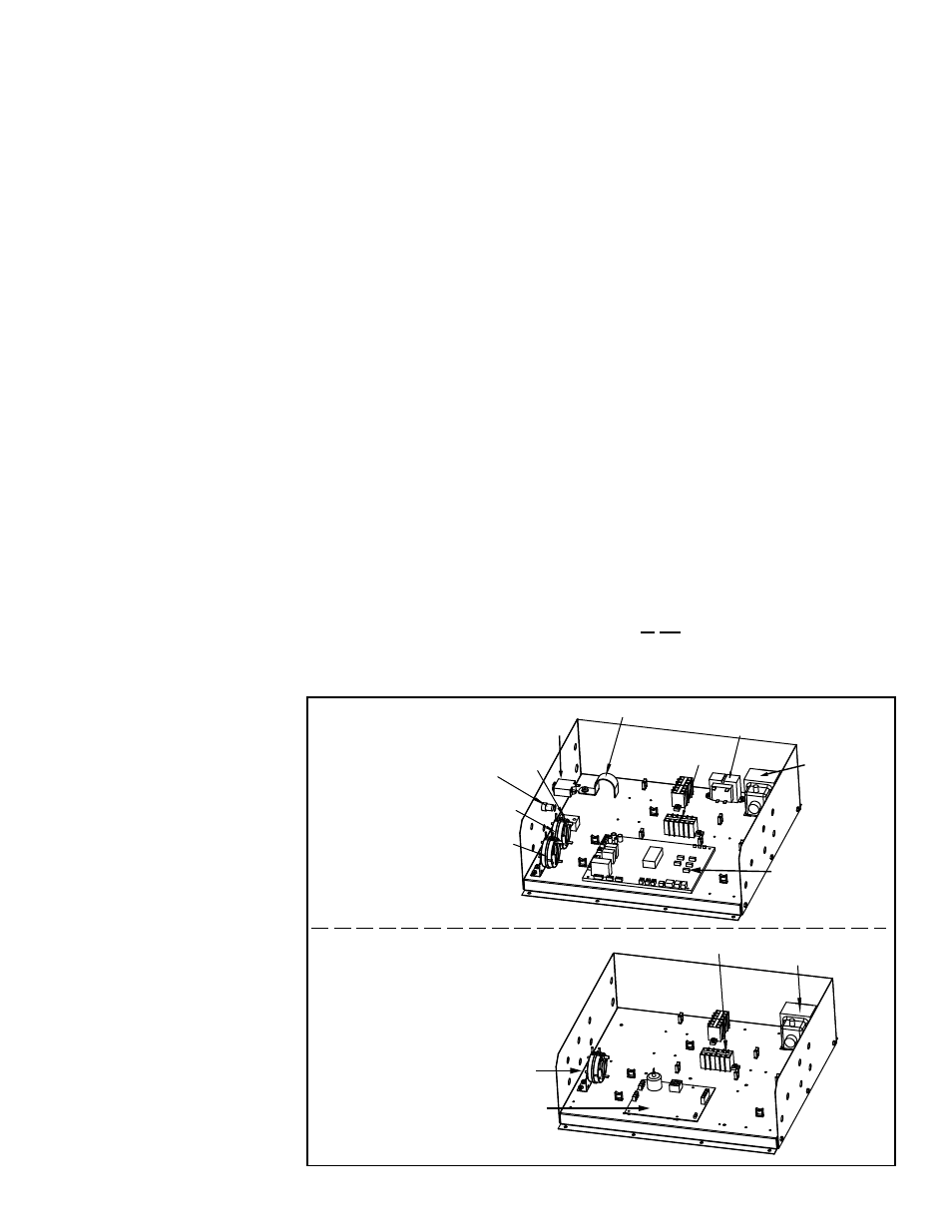
FIGURE 12 - Gas Heat
Section Controls in a
MAPSIII "D" Cabinet
The heat section controls
are located on the floor
of the heat section; .see
FIGURE 1, page 4.)
Terminal Blocks
Pressure Switch
(Combustion Air)
Transformer
75VA
Ignition Board (See FIGURE 14.)
Gas Heat Section
Electrical Box -
Applies to All Sizes
(furnace with modulating burner)
Gas Heat Section Electrical Box -
Applies only to Sizes 1000, 1200,
1400, 1600 with two furnace
sections
(Non-modulating heat section
is closest to the blower.)
Terminal
Blocks
Pressure
Switch
(Airflow)
Pressure Switch
(Combustion Air)
PAM
Relay
Venter Motor Capacitor Bracket
Transformer 30VA
Transformer
75VA
Modulating Ignition
Board with ID Plug
(See FIGURE 13A.)
Fuse
Holder
Thermal Circuit
Breaker
NOTE: Configuration of
heat sections in relation to
the blower depends on date
of manufacture. Currently
manufactured systems with
two heat sections have the
non-modulating furnace
closest to the blower and
the modulating furnace
downstream. Previously
manufactured systems
may have the opposite
configuration.
IMPORTANT NOTE: The information in Section 4.2 applies to standard natural gas
MAPSIII D Cabinet Models RDCB and RDDB manufactured beginning 12/2011. A
Model RDCB or RDDB manufactured prior to 12/2011 may also have these gas control
components. The identification of the ignition board in the Serial No. on the heat sec-
tion rating plate will determine whether this information applies. If the ignition code in
the serial number is 96, the information in Section 4.2 applies. If the ignition code is 90,
91, 92, or 93, contact your representative or distributor or search RezSpec.com for a
previous version of this manual.
Serial No. Sample: 3 BKH 789 BK 08 N 96 7D
Also, if the unit is propane ("N" in the Serial No. is an "L"), modulation control informa-
tion here does not apply. Refer to the rating plate or contact your distributor for infor-
mation.