Reznor MAPS III, Cabinet D RECB Users Manual User Manual
Page 23
Form O-MAPSIII Cabinet D, P/N 222918R9, Page 23
4.1.2 Instructions for
Inspecting / Cleaning
the Burner
NOTE: With the burner
removed, it is possible to
check the bottom of the
heat exchanger. See Para-
graph 4.1.1
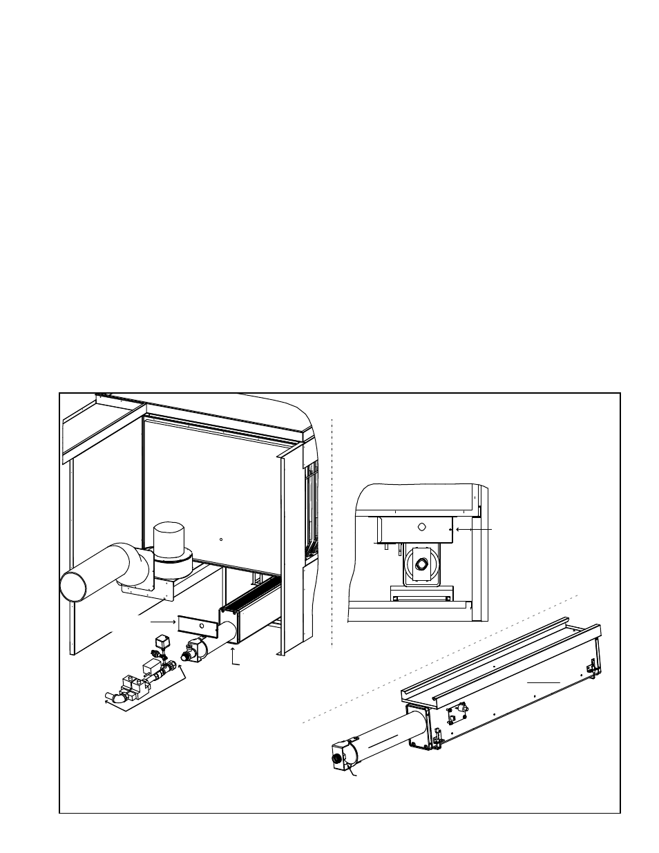
The burner will slide out of the unit. Refer to
FIGURE 9 and follow the instructions
below to remove and inspect the burner
1. Disconnect the gas train at the two unions showing in FIGURE 9. Do not allow the
portion of the gas train attached to the venturi tube to rotate.
Slide the "free" section of gas train that includes the valves to the left out of the
path of the slide-out burner. Do not disconnect the valve wires.
2. Loosen the screw holding the burner end shield. Remove the burner end shield
with the screw attached.
3. The burner is designed to slide out of the heater for inspection and/or service.
Remove the screws above and below holding the burner assembly. Carefully
pull the burner assembly (with pipe nipple attached) partially out of the cabinet.
To completely remove the burner, mark and disconnect the sensor wires and the
igniter and igniter board wires, and slide the burner out.
4. With the burner assembly removed, shine a flashlight on the burner ribbons. Look
for carbon buildup, scale, dust, lint, and/or anything that might restrict flow through
the spaces between the burner ribbons. Holding the burner assembly so that any
foreign material will fall away from the burner, use a stiff bristle brush to loosen
and remove any foreign material(s). If the burner is excessively dirty, remove both
With the burner removed in Paragraph 4.1.2, shine a light into each heat
exchanger section. With the light shining into the heat exchanger, observe the
outside for visible light. Repeat this procedure with each heat exchanger section. If
any light is observed, replace the heat exchanger.
If it is determined that the heat exchanger needs to be replaced, contact your
distributor or representative for replacement information.
FIGURE 9 - Remove
the Burner/Venturi
Assembly
Direct View of the Burner
after the Gas Train has
been disconnected.
Loosen screw
to remove
burner end
shield.
Break the gas train at the union
before and the union after the controls.
Be careful not to rotate the portion of
the gas train connected to the venturi/
burner. Slide disconnected “valve section”
of the gas train to the left so that it will be
out of the path of the slide-out burner.
Venturi/Burner
Asembly
Burner End
Shield
Burner/Venturi
Assembly
DSI Module
Ignitor
Assy
Flame
Sensor
Burner
Venturi
Orifice