Maintenance/ service procedures (cont'd), 6 compressor maintenance (cont'd) – Reznor MAPS III, Cabinet D RECB Users Manual User Manual
Page 16
Form O-MAPSIII Cabinet D, P/N 222918R9, Page 16
□
Step 10. System Startup
Assure voltage to compressor does not drop below minimum allowable voltage
(e.g. 187 volts for 230/208-3-60, 415 volts for 460/3/60, 518 volts for 575/3/60)
during the period the compressor is trying to start.
If a low voltage or voltage
imbalance condition exists, the electrical problem must be determined and
corrected prior to operating the unit.
Voltage Imbalance - Voltage imbalance is becoming a more common problem.
In a 3-phase system, excessive voltage imbalance between phases will cause
motors to overheat and compressors to fail. Maximum allowable imbalance is
2%. To determine voltage imbalance, measure and record the voltage of all three
phases. Take the measurements at the compressor terminals with the compressor
operating.
Voltage Imbalance Formula:
Key:
V1, V2, V3 = line voltages as measured
VA (Average )= (V1 + V2+ V3) / 3
VD = Line Voltage (V1, V2, or V3 that deviates farthest from average (VA)
Formula:
% of Voltage Imbalance = [100 (VA - VD)] / VA
If the imbalance is within the 2% tolerance, voltage imbalance is not a problem and
the system may be operated. If the imbalance exceeds the 2% tolerance, follow
the procedures below.
Solutions to Voltage Imbalance:
The cause for a voltage imbalance problem can originate at the power company or
can be caused inside the building. Try the following on-site solution to determine if
the problem can be easily resolved.
Roll the connections at the compressor terminals one forward. Connect the wire
now on Terminal 1 to Terminal 2, 2 to 3, and 3 to 1. Re-measure and re-calculate
the voltage imbalance. If the imbalance is within 2%, the system may be operated.
If the imbalance is not within tolerance, roll the connections one more forward.
Re-measure and re-calculate the voltage imbalance. If the imbalance is within
2%, the system may be operated. If the voltage imbalance still exceeds 2%, do
not start the system. Contact the building owner or person responsible to have an
electrician analyze the buildings's power supply and load distribution.
Power Supply Voltage Phasing - Connect refrigerant pressure gauges to the
suction and discharge lines of the compressors and an electric meter to the power
supply.
3.6 Compressor
Maintenance
(cont'd)
3. Maintenance/
Service
Procedures
(cont'd)
□
Step 9. Charge the
System (cont'd))
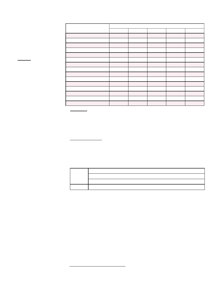
Approximate R410-A Refr
igerant Charge (lbs) by Model Size and
Compressor for Each Circuit (See FIGURE 5, page 12, to identify location.)
D Cabinet Models
and Size
Compressor Circuit
A
B
C
D
E or DH
RCB/RDCB/RECB 360
10.0
N/A
13.0
6.0
N/A
RCB/RDCB/RECB 480
10.0
13.0
13.0
N/A
N/A
RCB/RDCB/RECB 600
10.0
10.0
13.0
13.0
N/A
RCB/RDCB/RECB 720
13.0
13.0
13.0
13.0
N/A
RDB/RDDB/REDB 418
10.0
N/A
13.0
6.0
9.0
RDB/RDDB/REDB 444
10.0
N/A
13.0
6.0
9.0
RDB/RDDB/REDB 484
10.0
N/A
13.0
6.0
11.0
RDB/RDDB/REDB 538
10.0
13.0
13.0
N/A
9.0
RDB/RDDB/REDB 564
10.0
13.0
13.0
N/A
9.0
RDB/RDDB/REDB 602
10.0
13.0
13.0
N/A
11.0
RDB/RDDB/REDB 658
10.0
10.0
13.0
13.0
9.0
RDB/RDDB/REDB 684
10.0
10.0
13.0
13.0
9.0
RDB/RDDB/REDB 722
10.0
10.0
13.0
13.0
11.0
RDB/RDDB/REDB 804
13.0
13.0
13.0
13.0
9.0
RDB/RDDB/REDB 842
13.0
13.0
13.0
13.0
11.0