Reznor MAPS III, Cabinet D RECB Users Manual User Manual
Page 39
Form O-MAPSIII Cabinet D, P/N 222918R9, Page 39
Normal Furnace Operation Display
LED Display
Heat Mode
Description
OFF Mode (OFF)
System Idle - Control board has power, no faults found, no call for heat.
PURGE Mode (Pur)
System is purging the heat exchanger – No gas on, no flame, venter motor runs for the
specified purge timings. Purge cycles occur immediately before and after each burner
operation.
IGNITION Mode (Ign)
System is initiating burner operation – Ignitor energized, modulating valve moved to
ignition setting, gas on. Maintained for the trial-for-ignition period and the five-second
flame stabilization period.
WARM-UP Mode (HEA)
- (Board Self Check)
Period between Ignition and Run – System checks completed before modulation
control begins.
RUN Mode (run)
Normal modulating operation.
Ignition Retry (rEt)
System has had a failed ignition attempt or has lost flame during burner operation and
is beginning another ignition cycle.
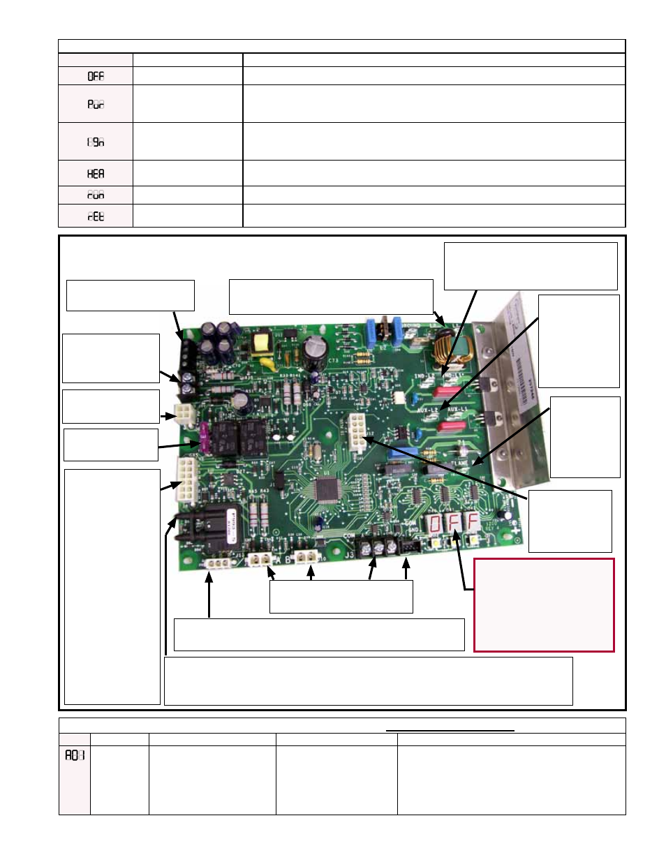
3 Character LED
Display used to show
deep modulation
board codes for
status, alarm, and
error information.
ID Plug
(unique by
heat section
size)
Deep Modulation (Option AG70) Ignition Board is in
the Heat Section (See FIGURE 12, page 25.)
IQ Controller Signal
Input Terminals (J4)
Board Status
Voltage Output
to IQ (J7)
Board Power
and Signal (J6)
Control Board
Fuse (3A)
Plug Connec-
tion for Board
Control Points
(J8)
• Ball Valve
Actuator Power,
Drive Voltage,
and Feedback
Signal
• Off Board
Digital Venter
Air Pressure
Switch and Unit
Primary Limit
Switch
On board Air Pressure Sensor for Monitoring Inducer Pressure.
Venter Sensing Tubing is connected from Venter housing to
"LO" pressure input point on air sensing transducer.
Gas Manifold PSI Transducer Plug 3-wire (red,
black, and green) Wiring Connection (J13)
J9, J10, J3, and J2 are
not currently used.
Flame
Sensor
Spade
Connec-
tion
(T8)
Inducer
Motor
Capacitor
Spade
Connection
(AUX-L2
T6
)
Inducer Motor Main Power
Connection Spades
(IND-L2
T3
and IND-L1
T2
)
Main Board Supply Power Input
Spades (L1
T1
and L2
T5
)
Gas Heat Section Modulating Control FUNCTIONAL ALERTS
Code
Alert
Description
Probable Causes
Solutions
Failed ignition
attempt (AO1)
Maximum
number of
allowed retries
not met
The flame could not be
established during the trial for
ignition period. This alert indicates
the maximum number of retries
has not been exceeded and
furnace operation will continue
with another ignition attempt.
See in the LOCKOUT ERRORS
section, pages 41-42.
See in the LOCKOUT ERRORS section, pages 41-42.