3 gas train – Reznor MAPS III, Cabinet D RECB Users Manual User Manual
Page 30
Form O-MAPSIII Cabinet D, P/N 222918R9, Page 30
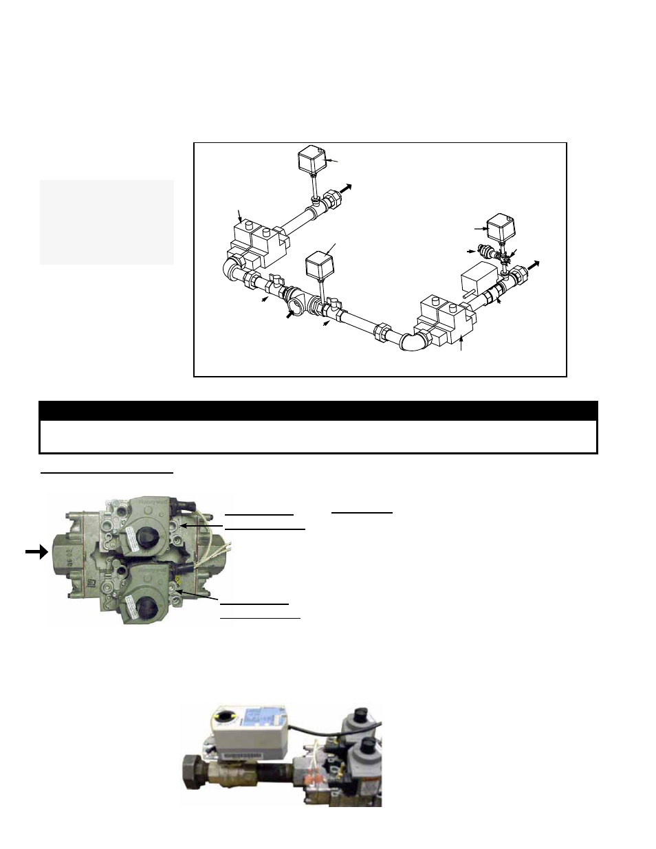
Location: The gas train is visible with the heat section door open. See component
identification in
FIGURE 15.
Service: Carefully remove external dirt from the valves and check the wiring connec-
tions. Annually, in preparation for the heating season, check the dual, single-stage
operating valve to be sure that it shuts gas flow off completely.
If any gas valves or other gas train components need to be replaced, they must be
replaced with identical part or factory-authorized replacement.
Optional
Low Gas
Pressure
Switch
Manual
Shutoff Valve
(2nd furnace)
Dual, Single-Stage
Gas Valve (non-
modulating furnace)
Gas
Supply
Manual
Shutoff Valve
(1st furnace)
Ball Valve
with Actuator
(modulating
furnace)
Dual, Single-Stage Gas Valve
(modulating furnace)
Transducer
Optional High Gas
Pressure Switch
Pressure
Tap
Optional High Gas
Pressure Switch
FIGURE 15 - Gas
Train Components
NOTE: Heat section
Sizes 500, 600, 700, and
800 with one furnace
have manifold for
modulating furnace
only.
Dual Single-Stage Operating Gas Valve - All gas heat sections have one or two dual single-stage gas valves.
WARNING
he operating valve is the prime safety shutoff. All gas supply lines must be free of dirt or
scale before connecting to the unit to ensure positive closure. See Hazard Levels, page 2.
3) Use your finger to fully block the burner orifice. Continue blocking the orifice for
several seconds and observe the manometers. If any pressure is indicated, the
gas valve is leaking. A leaking gas valve must be replaced before the heater is put
back in operation.
4) Repeat the test with each dual single-stage gas valve.
FIGURE 17 - Ball
Valve and Actuator
in Modulating Gas
Control
The modulating furnace has a ball valve
with an actuator to control gas flow. The
ball valve and actuator are located down-
stream of the dual single-stage valve as
shown here.
Carefully clean external dirt accumula-
tion from the actuator.
1/8” Outlet
Pressure Tap
1/8” Outlet
Pressure Tap
FIGURE 16 - Top View of Dual Single-Stage
Gas Valve
The dual single-stage gas valve(s) must be checked
annually to ensure that each valve is shutting off gas flow
completely.
Instructions:
1) Locate the 1/8" NPT pressure taps on the
combination valve (see illustration on the left).
2) Turn the manual valve OFF to prevent flow to the
manifold. Connect a manometer to both of the 1/8”
outlet pressure taps.
NOTE: Manometers (fluid-
filled gauges) with inches water column scale are
recommended. Turn the manual valve ON and the
heater off.
4. Gas Heat
Section
Maintenance
(cont'd)
4.3 Gas Train