8 dampers and damper controls, 9 other controls, Inlet air dampers – Reznor MAPS III, Cabinet D RECB Users Manual User Manual
Page 19: Damper motor 2-position damper motor (option ar8), Modulating motor (option ar25), 1 programmable digital controller and sensors, I/q system controller display
Form O-MAPSIII Cabinet D, P/N 222918R9, Page 19
3.8 Dampers
and Damper
Controls
Inlet Air Dampers
Location: Dampers and damper motors are located in the inlet air opening.
Function: Dampers operate in response to the control selected. Damper controls are
shown below.
Service: Clean dampers and controls of dust and dirt.
Service: Other than external cleaning, there is no service required on the dampers or
the damper motor. If the damper, control, or motor need to be replaced, replace with a
factory-authorized replacement.
For additional information on damper controls (Options GF 1-9), see the system instal-
lation manual Form I-MAPSIII Cabinet D.
Damper Motor
2-Position Damper Motor (Option AR8)
Function: The 2-position damper motor opens and closes the dampers in response to
unit operation or a field-supplied time clock.
Motor closes dampers on heater shutdown.
Modulating Motor (Option AR25)
Function: The modulating damper motor actuates the dampers in response to I/Q
control with actuation from input switch settings, a remote potentiometer, building pres-
sure, CO2, 2-position outside air enthalpy, or dual reference enthalpy. Motor closes
dampers on heater shutdown.
Model & Size
Compressor Circuit
P/N
Sporlan No. Connection Sizes
RCB/RDCB/RECB
600
RDB/RDDB/REDB
658/684/722
A
220556
BBIZE-8-GA
5/8x7/8x1/4
B
220556
BBIZE-8-GA
5/8x7/8x1/4
C
220558
BBIZE-15-GA
7/8x1-1/8x1/4
D
220558
BBIZE-15-GA
7/8x1-1/8x1/4
E or DH (RDB/RDDB/REDB 658 only)
234987
BBIZE-4-GA
1/2x7/8x1/4
E or DH (RDB/RDDB/REDB 684 only)
220555
BBIZE-6-GA
5/8x7/8x1/4
E or DH (RDB/RDDB/REDB 722 only)
220556
BBIZE-8-GA
5/8x7/8x1/4
RCB/RDCB/RECB
720
RDB/RDDB/REDB
804/842
A
220558
BBIZE-15-GA
7/8x1-1/8x1/4
B
220558
BBIZE-15-GA
7/8x1-1/8x1/4
C
220558
BBIZE-15-GA
7/8x1-1/8x1/4
D
220558
BBIZE-15-GA
7/8x1-1/8x1/4
E or DH (RDB/RDDB/REDB 804 only)
220555
BBIZE-6-GA
5/8x7/8x1/4
E or DH (RDB/RDDB/REDB 842 only)
220556
BBIZE-8-GA
5/8x7/8x1/4
3.9 Other Controls
Other factory-installed standard and optional controls are illustrated below. Find their
location in
FIGURE 1, page 4. Cleaning external dirt is the only service procedure. If
any need to be replaced, use only factory-authorized replacement parts.
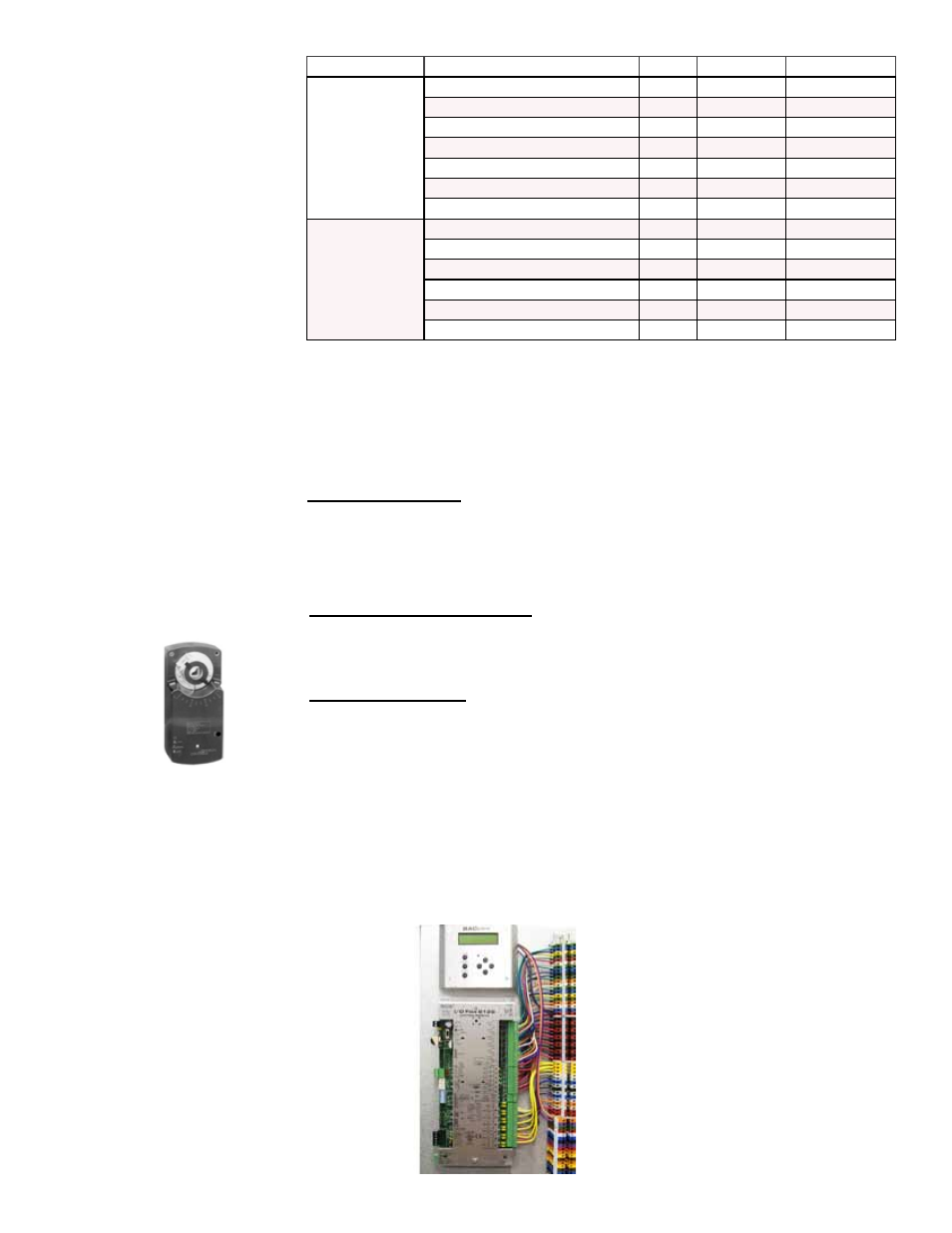
3.9.1 Programmable Digital Controller and Sensors
All MAPSIII systems have a unit-mounted,
24-volt programmable I/Q controller.
Depending on how it was ordered, the system
is equipped for either neutral air/discharge air
control (Option D15) or space control with
discharge air reset (Option D16). The control-
ler is factory programmed to match the selec-
tion. See the control instruction manual for
more information.
Some sensors are standard and others will
depend on option selection.
NOTE: Refer to Control
Instruction Form
CP-MAPSIII D15/D16
for information on the
programmable controller.
I/Q System
Controller
Display