0 troubleshooting (cont'd), Ignition module troubleshooting flow chart – Reznor MAPS III, Cabinet D RECB Users Manual User Manual
Page 38
Form O-MAPSIII Cabinet D, P/N 222918R9, Page 38
Control Status - Green LED Codes
Steady ON ...... Normal Operation, No call for heat
Fast Flash ....... Normal Operation, Call for heat
1 Flash ............ System Lockout, Failed to detect or sustain flame
2 Flashes ........ Pressure Switch Did Not Close within 30 Seconds of Venter Motor
3 Flashes ........ High Limit or Flame Rollout Switch Open
4 Flashes ........ Pressure Switch is Closed Before Venter Motor is Energized
Steady OFF .... Blown fuse, No Power, or Defective Board
Flame Status - Yellow LED Codes
Steady ON ...... Flame is sensed
Slow Flash ...... Weak flame (current below 1.0 microamps ± 50%)
Fast Flash ....... Undesired Flame (valve open and no call for heat)
Operating and
Troubleshooting
Indicator Lights
on Control Module
used on the non-
modulating furnace
on Sizes 1000, 1200,
1400, and 1600
6.2 Troubleshooting Heat Section (cont'd)
Trial for Ignition
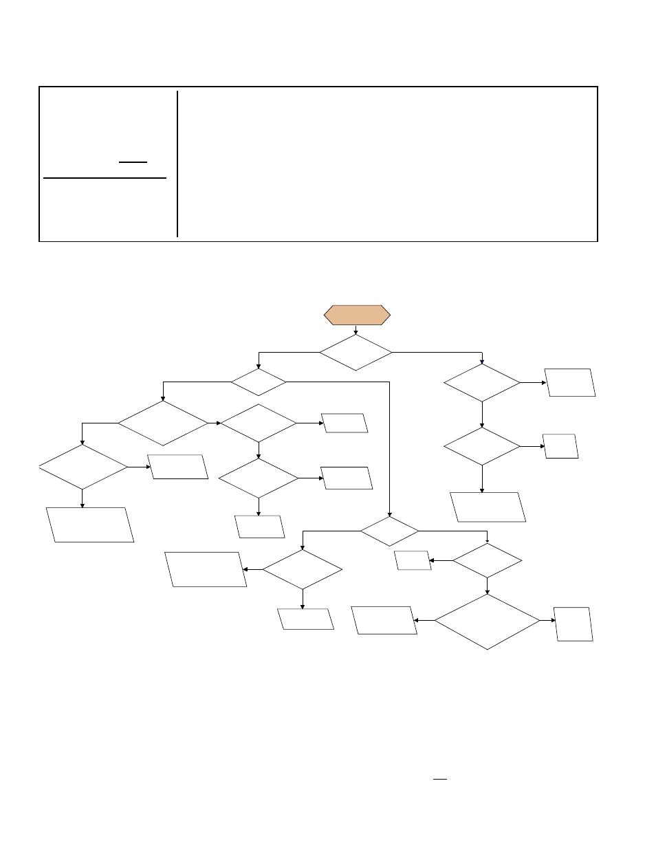
Call for Heat
Is there a
spark across gap at
ignitor?
Does gas
ignite?
Is there
minimum flame
current at the flame
sensor?
Is there
minimum flame
current at the control
module?
Replace control
module.
Check connections to
flame sensor or
moisture in bulkhead
connector.
Is the
flame sensor
corroded?
Clean flame
sensor.
Is the sensor
located in flame
correctly?
Replace flame
sesnsor.
Repositon
flame sensor.
Is gas
flowing?
Is the ignitor
position correct in the
gas flow?
Check gas pressure
and supply voltage. If
either are low, correct
and repeat startup.
Reposition
spark ignitor.
Is there
24VAC at the gas
valve?
Is there
24VAC from gas
valve output on control
module
to chassis?
Check wiring and
connections to
gas valve.
Replace
ignition
control
module.
Replace
gas valve.
Is there
spark voltage at
control?
Check high
voltage wire
continuity.
Is there
24V P1-2 to power
control?
Replace
control
module.
Check wiring
and/or 24VAC
transformer output.
YES
NO
YES
NO
YES
NO
YES
NO
YES
NO
YES
NO
YES
NO
YES
NO
NO
YES
YES
NO
YES
NO
YES
NO
Ignition Module
Troubleshooting
Flow Chart
Do not attempt to repair the DSI integrated control module (circuit board); the only field replaceable component is the
fuse.
IMPORTANT: When using a multimeter to troubleshoot the 24 volt circuit, place the meter’s test leads into the 5 or
9 pin connectors located on the ignition control. Do not remove connectors or terminals from the electrical components.
Doing so can result in misinterpreted readings due to the ignition control board’s fault mode monitoring circuits.
6.2.2.2
Troubleshooting
the Heat Section
Control Module (deep
modulation board)
used with Modulating
Gas Control
The control module
(P/N 257246) that operates the furnace in a MAPSIII Cabinet D
system has a built-in, self-diagnostic capability. The control continuously monitors its
own operation and the operation of the system. The LED on the control indicates the
current state, warnings, failures, and test modes.
IMPORTANT NOTE: The troubleshooting information applies to the control board that
is standard on MAPSIII D Cabinet Models RDCB and RDDB manufactured beginning
8/2011. A Model RDCB or RDDB manufactured prior to 8/2011 may have this board.
The ignition board is identified as
"96" in the Serial No. on the heat section rating plate.
Serial No. Sample: 3 BKH 789 BK 08 N 96 7D
If the ignition code in the serial number is 96, the following troubleshooting information applies. If the ignition code is 90,
91, 92, or 93, contact your representative or distributor or search RezSpec.com for a previous version of this manual.
6.0 Troubleshooting
(cont'd)
6.2.2 General Troubleshooting - Gas Heat Section (cont'd)
6.2.2.1 Troubleshooting the non-modulating furnace (cont'd)