Reznor MAPS III, Cabinet D RECB Users Manual User Manual
Page 26
Form O-MAPSIII Cabinet D, P/N 222918R9, Page 26
4.2 Gas Heat Section Controls
4. Gas Heat
Section
Maintenance
(cont'd)
4.2.2 Ignition System (Natural Gas only)
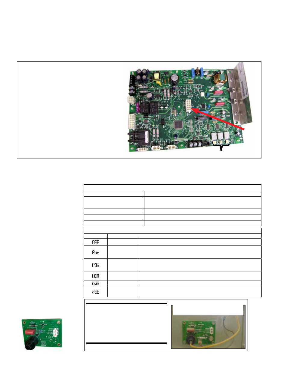
The modulating furnace has the control module in the control compartment (
FIGURES
12 and 13A) with an additional board (FIGURE 13B) attached directly to the side of
the burner to control spark. Do not attempt to disassemble either board. However, each
heating season check the lead wires for insulation deterioration and good connections.
If replacement is required, these boards must be replaced with identical parts.
FIGURE 13A - Ignition Control
Module (Deep Modulation Board)
The control has a built-in, self-diagnostic capability. The control continuously monitors
its own operation and the operation of the heat section including direct spark ignition,
safety and modulating valves, and venter motor speed. The 3-digit display on the con-
trol indicates the current system state, warnings, failures, and test modes.
3-Character Display
ID
Plug
IMPORTANT: The control module illustrated
is
P/N 257246 used on all MAPSIII Cabinet
D heat sections manufactured beginning
8/2011 and on previously manufactured
units as a special. The ID plug on each
board is unique for each size of heat section.
A replacement board will require either a
new ID plug or reuse of the ID plug from the
board being replaced.
Standard MAPSIII Cabinet D heat sections
manufactured prior to 8/2011 have a unique
ignition board by size and do not have a
replaceable ID plug.
Normal Furnace Operation (LED 3-Character Display in FIGURE 13A)
LED Display
Heat Mode
Description
OFF Mode (OFF) System Idle - Control board has power, no faults found, no call for heat.
PURGE Mode
(Pur)
System is purging the heat exchanger – No gas on, no flame, inducer runs for
the specified purge timings. Purge cycles occur immediately before and after
each burner operation.
IGNITION Mode
(Ign)
System is initiating burner operation – Igniter energized, modulating valve
moved to ignition setting, gas on. Maintained for the trial-for-ignition period
and the five second flame stabilization period.
WARM-UP Mode
(HEA)
Period between Ignition and Run – System checks completed before
modulation control begins.
RUN Mode (run)
Normal modulating operation.
Ignition Retry (rEt) System has had a failed ignition attempt or has lost flame during burner
operation and is beginning another ignition cycle.
Controller LED Information (displayed on power up)
Display Info (example only) Description
D CAb
Furnace series or model name, for example, "D cabinet
series"
500
Heat Section Size
nAt
Fuel type
1.01
Software version
NOTE: Operating and
Lockout Error Codes
displayed on ignition
controller 3-character
display (
FIGURE 13A) are
listed in Troubleshooting
Paragraph 7.3.3.
FIGURE 13B - Spark
Ignition (DSI) Board,
P/N 257975
Spark Board is attached
to the side of the burner.
CAUTION: Due to high
voltage on the spark wire
and electrode, do not
touch when energized. See
Hazard Levels, page 2.