Caution, Maintenance/ service procedures (cont'd), 6 compressor maintenance (cont'd) – Reznor MAPS III, Cabinet D RECB Users Manual User Manual
Page 18: 7 thermostatic expansion valves, Step 11 . check subcooling and superheat. (cont'd)
Form O-MAPSIII Cabinet D, P/N 222918R9, Page 18
Follow the procedures in Paragraph 3.5 to check subcooling and superheat.
□
Step 12. (Select the procedure that applies.)
IF the oil measured in Step 2 was significantly less than in the table on
page 12 or the acid test in
Step 2 indicated a burnout, do the following:
a) Operate the unit for several hours. Check the pressure drop through the
temporary suction line filter drier. If the pressure drop exceeds 8 psig, recover
the refrigerant, replace the suction line filter drier with the same type as
removed, replace the liquid line filter drier, evacuate the circuit, and re-charge
with the recovered refrigerant.
Continue to monitor the pressure drop through the suction line filter drier and
repeat the process above until the pressure does not exceed 8 psig after
several hours of operation. (NOTE: System must be allowed to run no more
than 72 hours with a suction line filter drier.)
b) Allow the system to operate for 4-8 hours. Recover the refrigerant and take an
oil sample. Retest the oil for acid.
c) If the test for acid is negative, remove the suction line filter drier, replace
the liquid line drier, evacuate, and re-charge the system with the recovered
refrigerant.
If the test indicates acid, replace both the liquid line filter drier and the suction
line filter drier and repeat b) and c).
CAUTION:
After cleanup is complete, remove the suction line
filter drier. See Hazard Levels, page 2.
d) Verify subcooling and superheat (refer to
Step 11).
e) When the system is operating properly, remove the gauges.
IF the oil measured in Step 2 was not significantly less than that shown
in the table on page 12 or the acid test in
Step 2 did not indicate a
compressor burnout, continue to the review in
Step 13.
□
Step 13 . Review ALL Steps to ensure that nothing was
overlooked.
3.6 Compressor
Maintenance
(cont'd)
3. Maintenance/
Service
Procedures
(cont'd)
□
Step 11. Check Subcooling and Superheat. (cont'd)
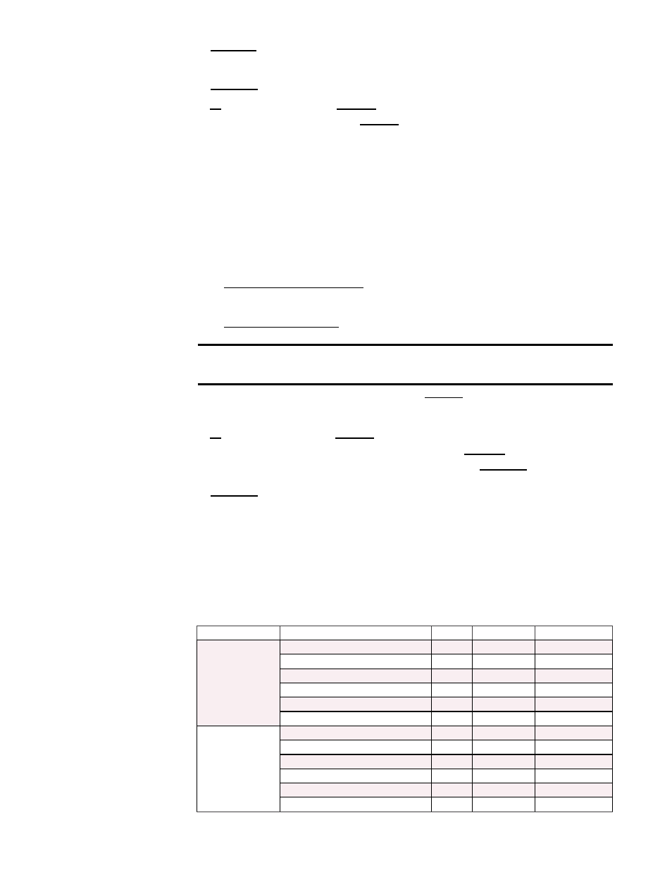
Model & Size
Compressor Circuit
P/N
Sporlan No. Connection Sizes
RCB/RDCB/RECB
360
RDB/RDDB/REDB
418/444/484
A
220556
BBIZE-8-GA
5/8x7/8x1/4
C
234987
BBIZE-4-GA
1/2x7/8x1/4
D
220558
BBIZE-15-GA
7/8x1-1/8x1/4
E or DH (RDB/RDDB/REDB 418 only)
234987
BBIZE-4-GA
1/2x7/8x1/4
E or DH (RDB/RDDB/REDB 444 only)
220555
BBIZE-6-GA
5/8x7/8x1/4
E or DH (RDB/RDDB/REDB 484 only)
220556
BBIZE-8-GA
5/8x7/8x1/4
RCB/RDCB/RECB
480
RDB/RDDB/REDB
538/564/602
A
220556
BBIZE-8-GA
5/8x7/8x1/4
C
220558
BBIZE-15-GA
7/8x1-1/8x1/4
D
220558
BBIZE-15-GA
7/8x1-1/8x1/4
E or DH (RDB/RDDB/REDB 538 only)
234987
BBIZE-4-GA
1/2x7/8x1/4
E or DH (RDB/RDDB/REDB 564 only)
220555
BBIZE-6-GA
5/8x7/8x1/4
E or DH (RDB/RDDB/REDB 602 only)
220556
BBIZE-8-GA
5/8x7/8x1/4
3.7 Thermostatic
Expansion
Valves
All refrigeration circuits have a thermostatic expansion valve. Thermostatic expansion
valves (TXV's) do not have replaceable parts. If a replacement valve is required, it
must be an R410-A valve and be sized correctly for the application. All refrigerant ser-
vice should be performed by a technician qualified in R410-A refrigerant.
Replacement valves by size and circuit are listed in the following table.