Reznor MAPS III, Cabinet D RECB Users Manual User Manual
Page 33
Form O-MAPSIII Cabinet D, P/N 222918R9, Page 33
Heat Section
Size
Modulating Burner Full Rate -
Natural Gas
Setpoint
OFF
Label
Color
Switch
P/N
Light Off
(Cold)
Equilibrium
(Hot)
500
2.6
2.6
1.0
Brown
201160
600
2.8
2.8
1.4
Red
201159
700
2.4
2.4
1.0
Brown
201160
800
2.7
2.7
1.4
Red
201159
1000
2.6
2.6
1.0
Brown
201160
1200
2.8
2.8
1.4
Red
201159
1400
2.4
2.4
1.0
Brown
201160
1600
2.7
2.7
1.4
Red
201159
Heat Section
Size
Gas Non-Modulating Burner Full
Rate - Natural Gas
Setpoint
OFF
Label
Color
Switch
P/N
Light Off
(Cold)
Equilibrium
(Hot)
1000
4.2
2.6
2.0
White
234054
1200
4.8
2.9
2.0
White
234054
1400
3.6
2.3
2.0
White
234054
1600
4.8
3.1
2.5
White
222860
Switch Settings
and P/N's
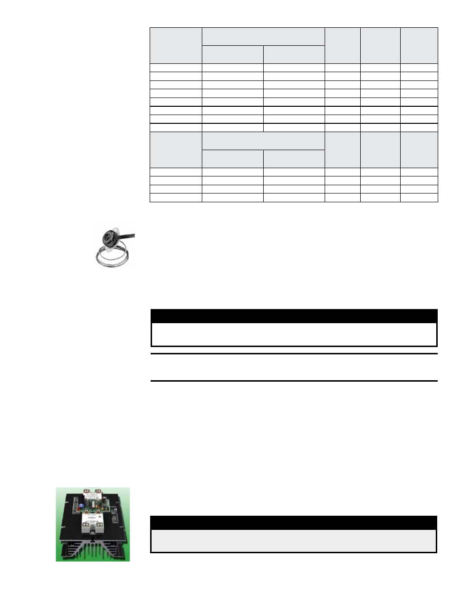
Location: A limit control is located in each heat section with the capillary sensor extend-
ing across the discharge side of the heat exchanger.
Function: The limit control is a temperature sensitive safety device. If the temperature
setting of the limit control is exceeded, the controller will shut down operation of the
heat section.
Service: The limit switch will automatically reset when the temperature drops. How-
ever, the cause for the limit activating should be found and corrected. If it is determined
that a limit control needs replacing, use only a factory-authorized replacement part that
is designed for the heat section size.
FIGURE 22 - Limit
Control
5.0 Electric Heat
Section
Maintenance -
Models RECB
and REDB
WARNING
Turn off the power locking the disconnect switch. Allow the
heating elements to cool.
CAUTION: Wearing eye protection is recommended when
cleaning the heating elements and cabinet.
Electric Heating
Elements and
Controls
Location: Refer to FIGURE 24, page 34.
Service: Check the heating elements at the beginning of the heating season. The ele-
ments are assembled and attached to the electrical panel that is visible on the inner
side of the electric heat section. Slide the panel out to access the elements. Carefully
clean all dust and dirt from the heating elements using a brush or steel wool. With a
vacuum or air hose, clean the inside of the cabinet especially the bottom and sides
where dirt and dust will accumulate.
If a replacement is needed, order a complete heat section assembly.
Location: See the control location illustration in FIGURE 1, page 4, and FIGURE 24
for additional electric heat section control panels. The electric heat section has one or
two SCR power controller(s), transformer, relay, digital controller, contactors, fuses,
and distribution blocks.
Quantities and types of fuses and contactors depend on the size of unit.
DANGER
High voltages are present on the terminals of the SCR power
controller(s).
If replacement parts are required, check with your distributor and use only factory-
authorized replacements.
FIGURE 23 - SCR
Controller