3 gas train (cont'd) – Reznor MAPS III, Cabinet D RECB Users Manual User Manual
Page 32
Form O-MAPSIII Cabinet D, P/N 222918R9, Page 32
4.0 Gas Heat Section Maintenance (cont'd)
4.3 Gas Train (cont'd)
Location: See FIGURE 12, page 25, for location.
Function: If the pressure switch does not sense combustion air flow from venter
operation, the controller will shut down heat section operation.
Service: If it is determined that the pressure switch needs replacing, use only
the factory-authorized replacement part that is designed for the model and size
of gas heater being serviced.
4.4 Other Gas Heat Section Controls
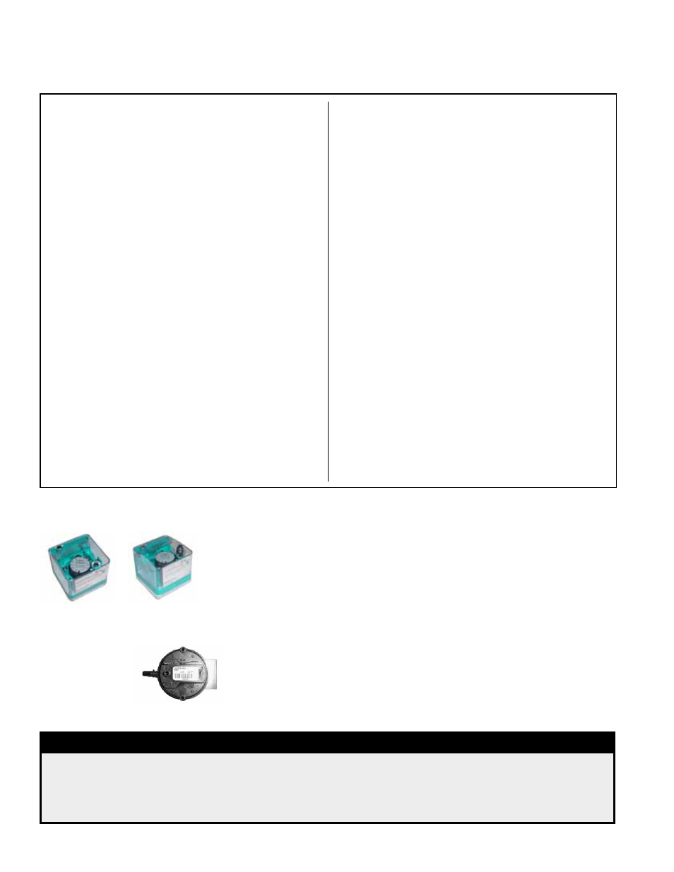
FIGURE 21 -
Combustion
Air Proving
Switch
FIGURE 20 - Optional Gas
Pressure Safety Switches
Location: Low pressure switch is at the entrance to the gas train. The high pres-
sure switch is at the burner end. See
FIGURE 15.
Function: To monitor gas pressure and shut down the heat section if gas pres-
sure becomes too low or too high. The low pressure switch is an auto reset type.
The high pressure switch requires manual reset.
Service: The are no replaceable parts and the settings are non-adjustable. If
replacement is required, use identical factory-authorized safety switches.
Modulating System Gas Valve Adjustment Instructions (cont'd)
DANGER
Safe operation requires proper venting flow. Never bypass the combustion air
proving switch or attempt to operate the heat section without the venter running
and proper flow in the vent system. Hazardous condition could result. See Hazard
Levels, page 2.
If the manifold pressure does not match the value in
the chart and the ball valve is fully or close to fully
open, adjust the pressure screws) on the Honeywell
valve (See
FIGURE 16) until the pressure matches
the chart. Adjust both pressure screws so that they
are the same. When the manifold pressure measured
at the manometer matches the pressure listed in the
chart, make a note for future reference of the position
of the ball valve stem in relation to the dash marks on
the actuator.
3. On the display, change the
ModHeat setting to
0% modulation and allow the ball valve to go to its
lowest setting. Check the manifold pressure on the
manometer. If the manifold pressure matches the Low
Setting value in the chart, skip to Step No. 4.
If the manifold pressure does not match the low (0%)
value on the chart, the ball valve will need to be
adjusted. Follow these steps:
a) While the unit is still firing at 0% modulation,
remove the ball valve actuator. To do this, locate
the screw on the rear of the actuator and remove
it. Loosen the actuator set screw (See
FIGURE
18), and carefully remove the actuator by lifting it
straight up. Do not disconnect any wires.
b) Using adjustable pliers, slowly turn the ball valve
stem until the manifold pressure on the manometer
matches the low setting on the chart.
Important NOTE: If the valve is adjusted too far
closed and the flame goes out, let the unit recycle
and then manually open the ball valve to the 100%
open position noted in Step No. 2. When the unit
is firing at full fire, re-attach the actuator to the ball
valve, and repeat the procedure beginning with
Step No. 2.
c) When the manometer readings match the values in
the chart and before re-installing the actuator, the
burr left on the ball valve stem from the previous
set screw setting needs to be removed. Either
lightly file the burr on the valve stem to prevent the
set screw from returning to the previous position
or remove the valve stem, rotate it 180° so that the
set screw contacts the opposite side of the stem,
and re-install the valve stem.
d) Re-install the actuator making sure it is level on the
ball valve mounting plate.
e) Re-check the setting by going to full fire (Set
ModHeat at 100%) and returning to 0% modulation
(Set
ModHeat at 0%). Measure the manifold
pressure. The adjusted gas pressure should be
close to the value in the chart on page 31. If not,
repeat the procedure.
4. When the settings are in agreement with the chart
and testing is complete, remove the manometer.
Set
ModHeat to 100%. Scroll the display back to
Test Mode and press Enter. Disable Test Mode by
pressing the
INC button to change the command from
ON to OFF; and press Enter.