Reznor MAPS III, Cabinet D RECB Users Manual User Manual
Page 27
Form O-MAPSIII Cabinet D, P/N 222918R9, Page 27
1) Call for Heat - The IQ controller calls for heat (there is a closure between "R" and
"W" and at least 2 VDC to the analog input). The ignition system circuit board will check
the modulating valve position and move to lightoff position. It checks to see that the limit
switch is closed and the pressure switch is open. If the pressure switch is closed, the
circuit board will wait indefinitely for the switch to open. If the switch is open, the circuit
board proceeds to prepurge.
2) Prepurge - After the actuator moves to its lightoff position, the circuit board ener-
gizes the venter motor and waits for the pressure switch to close. If the pressure switch
does not close at the beginning of a heat cycle, the venter motor will run for two min-
utes, then cycle off for 30 seconds, then on for two minutes, and so forth indefinitely.
When the pressure switch is proven closed, the venter motor ramps up to the appropri-
ate lightoff speed and the circuit board begins the prepurge time. If flame is present any
time while in prepurge, the prepurge time is restarted. If flame is present long enough to
cause lockout, refer to the Troubleshooting Guide in Paragraph 6.2.2. The ignition sys-
tem circuit board runs the venter motor for a 30-second prepurge time, then proceeds
to the ignition trial period.
3) Ignition Trial Period - The ignition system circuit board energizes the spark and
main gas valve. The venter remains energized. If flame is sensed during the first 6
seconds, the spark is de-energized. If flame has not been sensed during the first 6
seconds, the control de-energizes the spark output and keeps the gas valve energized
for an additional one second flame proving period. If flame is not present after the flame
proving period, the control de-energizes the gas valve and proceeds with three ignition
re-tries as specified in “Abnormal Heat Cycle, Ignition Retry”. If flame is present, the
circuit board proceeds to steady heat. After three re-tries, the board will lockout for one
hour. It will require a cycling of power to reset before the one-hour limit.
4) Modulating Heat - As long as the call for heat exists, the circuit board not only
modulates the gas to precisely meet varying load conditions, but also modulates the
combustion air to maintain stable performance and optimize thermal efficiency across
the entire modulating range. Circuit board inputs are continuously monitored to ensure
limit switch is closed and flame is established. When the call for heat is removed, the
ignition system circuit board de-energizes the gas valve and begins postpurge timing.
5) Post Purge - The venter motor output remains on for a 45 second postpurge period
after the system controller is satisfied.
Modulating Gas
Control Sequence of
Operation (single heat
section sizes and the
heat section furthest
from the blower on
dual heat section sizes
- natural gas only)
Ignition Controller on Non-Modulating Gas-Fired Furnace on MAPS D Sizes 1000, 1200,
1400, or 1600 with Two Furnaces
Control Status - Green LED Codes
Steady ON ...... Normal Operation, No call for heat
Fast Flash ....... Normal Operation, Call for heat
1 Flash ............ System Lockout, Failed to detect or sustain flame
2 Flashes ........ Pressure Switch Did Not Close within 30 Seconds
of Venter Motor
3 Flashes ........ High Limit or Flame Rollout Switch Open
4 Flashes ........ Pressure Switch is Closed Before Venter Motor is
Energized
Steady OFF .... Blown fuse, No Power, or Defective Board
Flame Status - Yellow LED Codes
Steady ON ...... Flame is sensed
Slow Flash ...... Weak flame (current below 1.0 microamps ± 50%)
Fast Flash ....... Undesired Flame (valve open and no call for heat)
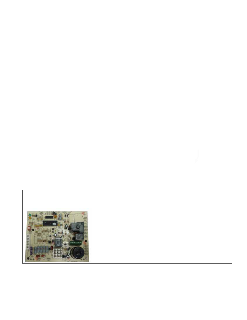
FIGURE 14 - DSI Integrated Control
Module (Ignition Board) used on
Non-Modulating Heat Section
DSI Integrated Control Module (ignition system circuit board) - See FIGURE 14.
The module is located in the control compartment and monitors the operation of the
gas heater including ignition. The green and yellow LED indicator lights flash to indi-
cate normal and abnormal conditions. If the heater fails to operate properly, check
these signals to determine the cause and/or to eliminate certain causes. The only
replaceable component is the 3 amp Type ATC or ATO fuse. If the fuse is blown, the
problem is most likely an external overload. Correct the problem and replace the fuse
(field supplied or P/N 201685).