Reznor MAPS III, Cabinet D RECB Users Manual User Manual
Page 31
Form O-MAPSIII Cabinet D, P/N 222918R9, Page 31
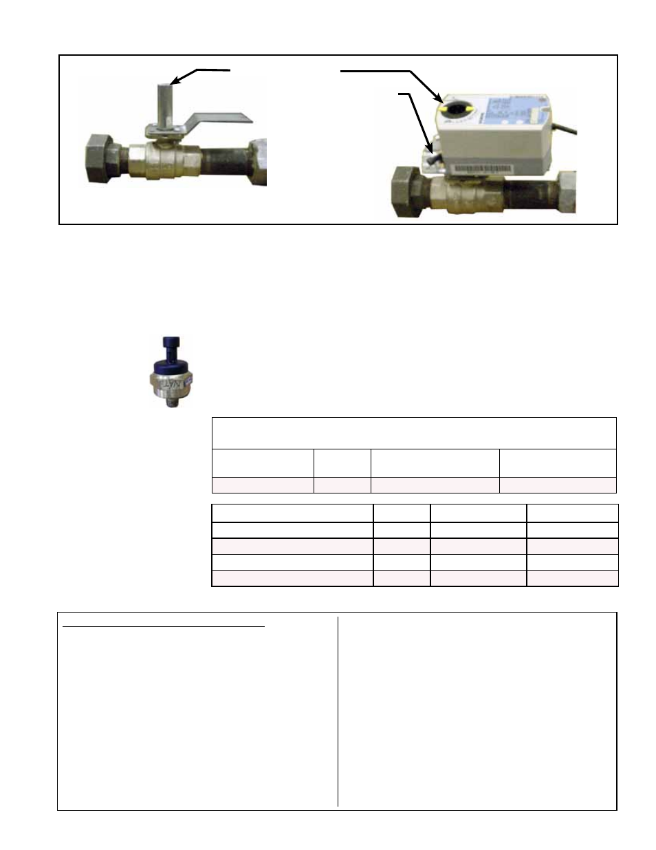
Ball Valve with actuator removed (for
illustration only); do not remove actuator.
Ball Valve Actuator
Modulates the Gas Flow
Actuator
Setscrew
(shown on the
right or closed
position)
Ball Valve Shaft
FIGURE 18 - Ball Valve with Actuator in Modulating Gas Control Manifold
FIGURE 19 -
Gas Manifold
Transducer
Location: See FIGURE 15.
Function: The transducer reads the manifold pressure and sets the venter motor
speed to precisely match the designed combustion settings.
Service: If the transducer needs to be replaced, use only a factory-authorized replace-
ment part designed for the purpose.
Modulating System
Gas Valve (Ball
Valve & Actuator)
Adjustment
Inspect the position of the ball valve shaft.
•
In the fully open position, the dash marks on the top of the shaft should be aligned
with the gas piping.
•
In the fully closed position, the dash marks on the top of the shaft should be
aligned at a 90° angle across the gas piping.
If the ball valve shaft is not properly aligned or if the manifold pressure does not match
the settings in the chart below, the ball valve will need to be adjusted.
Manifold Pressures
for MAPSIII Cabinet
D Gas Modulation
System
Manifold Pressure (" w.c.) Measured
at the Pressure Tap by the Gas Transducer
Cabinet and Heat
Section Size
Gas Type*
High Setting
100% on ModHeat
Low Setting
0% on ModHeat
D-Cab - All Sizes
Natural
3.4
0.20
Cabinet and Heat Section Size Gas Type High Setting 100% t Low Setting 50%
D-Cab 1000
Propane
10.0
5.0
D-Cab 1200
Propane
10.0
5.0
D-Cab 1400
Propane
10.0
5.0
D-Cab 1600
Propane
10.0
5.0
*NOTE: Propane is
available on limited sizes
with 2-stage gas control
only. Manifold pressures
(valve output) for those
sizes are listed below
.
To check and/or adjust gas modulation:
Checking modulation requires a manometer capable
of reading to 0.10" w.c. Connect the manometer as
instructed in Step 1.f) below.
To check and adjust the modulation system, the IQ
controller must be in
Test Mode. On the control display
in the electrical compartment, follow the steps below to
enter
Test Mode.
a) Scroll down to Menus and press Enter.
b) Enter password (0000) using the INC button and
the right arrow button and press
Enter.
c) Scroll down to the Service Menu and press Enter.
d) Scroll down to Test Mode and press Enter.
e) Scroll down to Manual Test; press Enter; press the
INC button to change the command from OFF to
ON; and press Enter.
f) After the system has completed the shutdown
sequence, connect the gas manometer to the
manifold pressure tap next to the transducer (See
FIGURES 15 and 19).
g) On the display, scroll down to Heat Stg 1 and press
Enter.
h) Scroll down to ModHeat which has a default setting
of 100%.
2. With the
ModHeat set at 100%, measure the manifold
pressure. If the manifold pressure matches the High
Setting value in the chart above, continue to Step No.
3.
Instructions