Input/output connectors, Red dsmc operation guide – RED DSMC User Manual
Page 187
COPYRIGHT © 2015 RED.COM, INC
RED DSMC OPERATION GUIDE
955-0020_V5.3, REV-J | 187
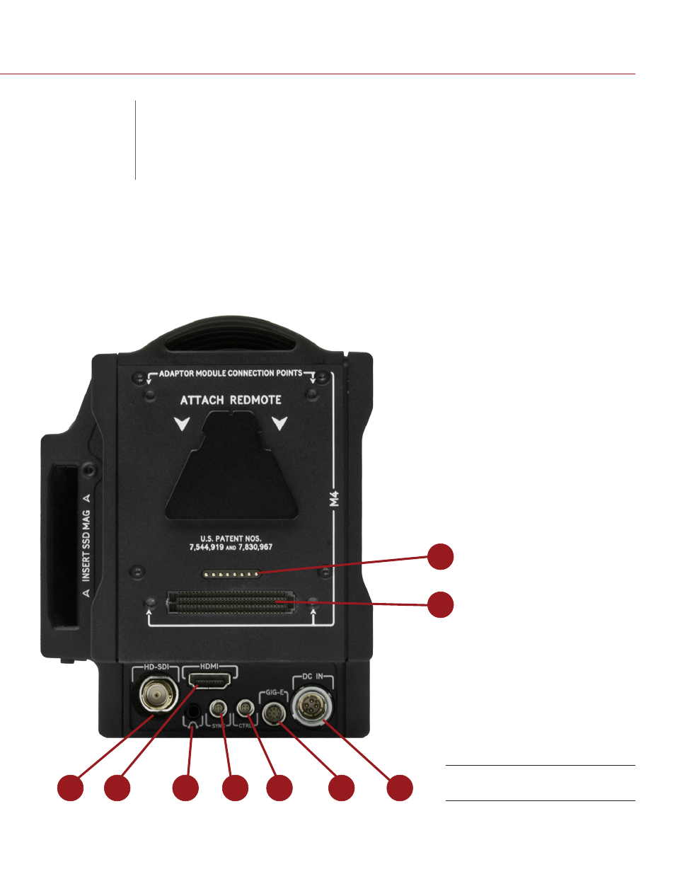
This appendix provides pinout information for the input/output connectors on the RED BRAIN.
NOTE: When connecting a cable to a connector, align the key and red marker on the cable connector with the
corresponding key and marker on the device connection.
NOTE: Connector diagram images are for reference only. Diagrams are not to scale.
3
4
5
6
7
8
9
1
2
DSMC Connectors
B
INPUT/OUTPUT
CONNECTORS