Gpio connector, Aux connector, Fan and temperature management – RED DSMC User Manual
Page 101: Red dsmc operation guide
RED DSMC OPERATION GUIDE
COPYRIGHT © 2015 RED.COM, INC
955-0020_V5.3, REV-J | 101
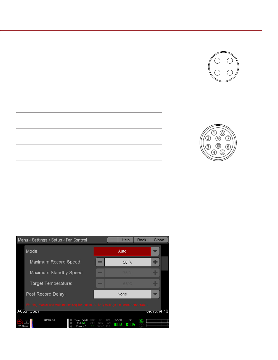
GPIO CONNECTOR
This table describes the I/O options for the GPIO connector on the Pro I/O Module:
I/O OPTION
DEFAULT ACTION
PIN
GPI A High
Key Disabled
2
GPI A Low
Record: Toggle
2
AUX CONNECTOR
This table describes the I/O options for the AUX connector on the Pro I/O Module:
I/O OPTION
DEFAULT ACTION
PIN
GPI B High
Key Disabled
6
GPI B Low
Record: Toggle
6
SW 1 High
Key Disabled
7
SW 1 Low
Go to: Playback
7
SW 2 High
Key Disabled
5
SW 2 Low
Record: Toggle
5
NOTE: For more information about the Pro I/O Module, see the
.
FAN AND TEMPERATURE MANAGEMENT
The DSMC is controlled by complex thermal algorithms to ensure that the sensor and camera operate at safe
temperatures. Each fan control mode affects the sensor temperature, sensor warm-up time, fan speed, and
resulting fan noise.
When selecting a fan mode, first take into consideration how each fan mode behaves, and then select a fan
mode that fits the needs of your project.
Regardless of sensor type and fan mode, you will get the best image quality by performing a black shading
calibration at the temperature you want to use for your shoot.
1
2
4
3