Hardware interrupt listing – Juniper Systems Allegro DOS Manual User Manual
Page 133
Allegro DOS Owner’s Manual 133
Hardware Interrupt Listing
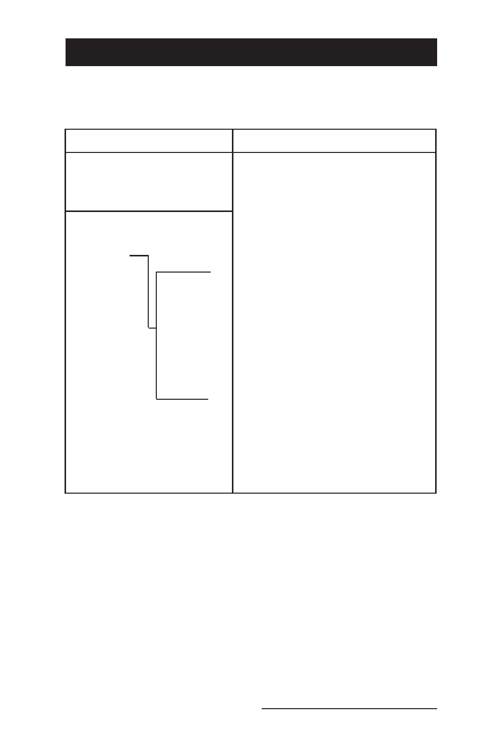
The following chart shows the interrupt-level assignments in
decreasing priority.
Level
Function
Microprocessor NMI
Parity or I/O Channel Check
Interrupt
Controllers
CTRL 1
CTRL 2
IRQ 0
Timer Output 0
IRQ 1
Keyboard (Output Buffer Full)
IRQ 2
Interrupt from CTRL 2
IRQ 8
Real Time Clock Interrupt
IRQ 9
Not Used*
IRQ 10
Not Used*
IRQ 11
Expansion Port UART
IRQ
12
Touchscreen
IRQ 13
Not Used
IRQ 14
Not Used*
IRQ 15
Not Used*
IRQ 3
Serial Port 2
IRQ 4
Serial Port 1
IRQ 5
Sound Chip
IRQ 6
Not Used
IRQ 7
Not Used*
*PC Card IRQ assigned by Card and Socket Services.
See also other documents in the category Juniper Systems Equipment:
- Allegro 2 Quick Start (1 page)
- Allegro 2 User Guide (119 pages)
- I/O module Allegro 2 (1 page)
- A2 Ethernet Dock (2 pages)
- A2 Ethernet Multi Dock (2 pages)
- Allegro MX User Guide (96 pages)
- Allegro MX Quick Start (1 page)
- AMXU GPS Expansion Pod (12 pages)
- Allegro Top Mounting Bracket (4 pages)
- Holux M-215+ for Allegro (2 pages)
- Holux GR-213 for Allegro (2 pages)
- Trimble Lassen GPS Expansion Pod (11 pages)
- Barcode Expansion Pod (22 pages)
- USB/Power Dock Pogo Pin (1 page)
- 12449 Alkaline (1 page)
- Allegro DAQ (28 pages)
- Allegro Desiccant Kit (5 pages)
- Allegro CX and CE Bluetooth CF Card (32 pages)
- Allegro CX Manual (304 pages)
- Allegro CX Quick Start (6 pages)
- Allegro DOS Manual (274 pages)
- Allegro DOS Quick Start (4 pages)
- Allegro DOS Quick Start (2 pages)
- Allegro CE Manual (292 pages)
- Allegro CE Quick Start (2 pages)
- Archer 2 User Guide (1 page)
- Archer 2 User Guide (133 pages)
- Archer 2 Quick Start (1 page)
- I/O module Archer 2 (1 page)
- Bumper kit Archer 2 (1 page)
- Handstrap kit Archer 2 (1 page)
- ikeGPS (16 pages)
- Archer Quick Start (2 pages)
- Archer Reference Guide (153 pages)
- Archer User Manual (384 pages)
- XF101 (2 pages)
- Travel Charger for the Ultra-Rugged Field PC (8 pages)
- Field PC Cap Replacement (1 page)
- Replacing the Communications Module on the Field PC (2 pages)
- ltra-Rugged Field PC Extended Caps (16 pages)
- Socket Bluetooth Card (6 pages)
- Mesa User Guide (112 pages)
- Mesa Addendum (1 page)
- Mesa Quick Start (2 pages)