Superbus 2000 automation module – Interlogix Concord 4 REV J Installation Manual User Manual
Page 33
Chapter 2: Installation
Concord 4 Installation Manual
27
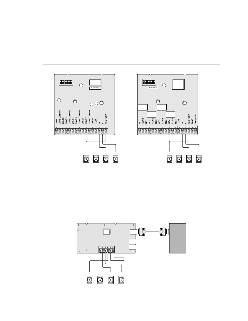
SuperBus 2000 8Z input and 4-relay output modules
Connect the modules to the panel as shown in Figure 22 below. Connect all
necessary input and output wiring using the module documentation.
Figure 22: Wiring input and output modules
Input module
Output module
GND +12V
A BUS B
GND +12V
A BUS B
SuperBus 2000 automation module
Connect the SuperBus 2000 automation module to the panel as shown in
Figure 23 below.
Figure 23: Connecting an automation device
Zone Com
Zone 1
GND
+12V
A Bus B
Automation module circuit board
Automation device
DB-9 serial cable
Panel terminals