Benchmark 2.0ln low nox boiler, Gf-123 – AERCO BMK 2.0 LN Natural Gas (SN G-11-1861 and above) User Manual
Page 90
Chapter 7
Benchmark 2.0LN Low NOx Boiler
GF-123
Maintenance
Installation, Operation and Maintenance Manual
OMM-0046_0E
Page 90 of 170
AERCO International Inc.● 100 Oritani Dr. ● Blauvelt, NY 10913. ● Ph: 800-526-0288 PR1 08/20/12
Part No.
Description
81101
Burner Gaskets (2)
81048
Flame Detector Gasket
81068
Blower Gasket
To inspect or replace the burner assembly:
1. Set the ON/OFF switch on the control panel, to the OFF position. Disconnect AC power from
the unit and turn off the gas supply.
2. Remove the side and top panels from the unit.
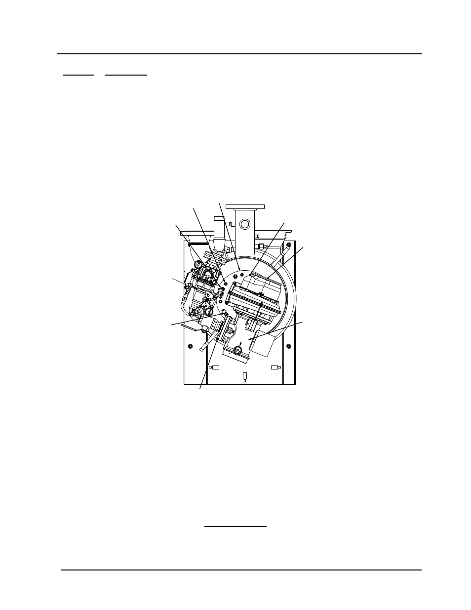
3. Disconnect the lead wire from the flame detector installed on the burner plate. See Figure 7-
5.
IGNITOR-
INJECTOR
3/8-16
NUTS (8)
BLOWER
BURNER
PLATE
AIR/FUEL
VALVE
FLAME
DETECTOR
STAGED
IGNITION
ASSEMBLY
1/2” BOLTS & NUTS (4)
CONNECT AIR/FUEL VALVE
TO GAS TRAIN
GROUNDING
SCREW
(10-32 x 1/2" LG.)
Figure 7-5:
Burner Assembly Mounting Details
4. Remove the two (2) screws securing the flame detector to the plate. The flame detector is
secured to the burner plate with one (1) #10-32 screw and one (1) #8-32 screw.
5. Remove the flame detector and gasket from the burner plate.
6. Disconnect the cable from the igniter-injector.
7. Using a 7/16” open-end wrench, disconnect the compression nut securing the gas injector
tube of the igniter-injector to the elbow of the staged ignition assembly (see Figure 7-2).
Disconnect the staged ignition assembly from the igniter-injector.
IMPORTANT
Prior to removing the igniter-injector, note the position of the gas injector
tube relative to the burner plate and blower. This is necessary to ensure
that the igniter injector is reinstalled in the proper orientation when it is
reconnected to the staged ignition assembly.