4 natural gas combustion calibration, Gf-123, Benchmark 2.0ln low nox boiler – AERCO BMK 2.0 LN Natural Gas (SN G-11-1861 and above) User Manual
Page 53
GF-123
Benchmark 2.0LN Low NOx Boiler
Chapter 4
OMM-0046_0E
I
nstallation, Operation and Maintenance Manual
Initial Start-Up
PR1 08/20/12
AERCO International Inc.● 100 Oritani Dr. ● Blauvelt, NY 10913. ● Ph: 800-526-0288
Page 53 of 170
4.4 NATURAL GAS COMBUSTION CALIBRATION
The Benchmark 2.0LN Boiler is combustion calibrated at the factory prior to shipping. However,
recalibration as part of initial start-up is necessary due to changes in the local altitude, gas BTU
content, gas supply piping and supply regulators. Factory Test Data sheets are shipped with
each unit. These sheets must be filled out and returned to AERCO for proper Warranty
Validation.
It is important to perform the following procedure as outlined. This will keep readjustments to a
minimum and provide optimum performance.
1. Open the water supply and return valves to the unit and ensure that the system pumps are
running.
2. Open the natural gas supply valve(s) to the unit.
3. Set the control panel ON/OFF switch to the OFF position.
4. Turn on external AC power to the unit. The display will show LOSS OF POWER and the
time and date.
5. Set the unit to the Manual Mode by pressing the AUTO/MAN key. A flashing Manual Valve
Position message will be displayed with the present rate in %. Also, the MANUAL LED will
light.
6. Adjust the air/fuel valve position to 0% by pressing the
▼ arrow key.
7. Ensure that the leak detection ball valve down-stream of the SSOV is open.
8. Set the ON/OFF switch to the ON position.
9.
Change the valve position to 29% using the ▲ arrow key. The unit should begin its start
sequence and fire.
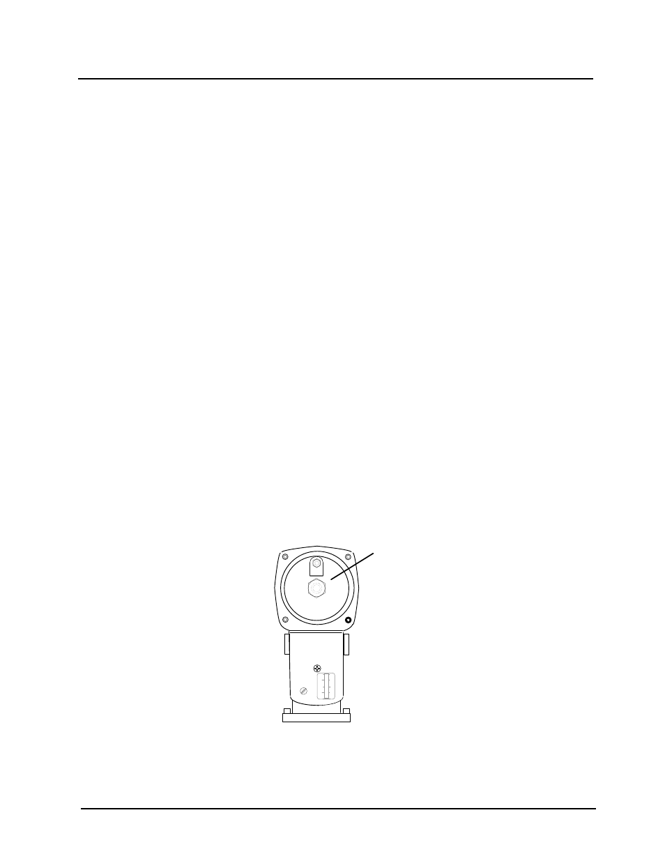
10. Next, verify that the gas pressure downstream of the SSOV is 2.8” W.C. for both FM and IRI
gas trains. If gas pressure adjustment is required, remove the brass hex nut on the
downstream SSOV actuator (IRI gas train) to access the gas pressure adjustment screw
(Figure 4-4). Make gas pressure adjustments using a flat-tip screwdriver to obtain 2.8” W.C.
BRASS HEX
HEAD CAP
(REMOVE TO
ACCESS GAS
PRESSURE
ADJUSTMENT
SCREW)
SSOV ACTUATOR
Figure 4-4: Gas Pressure Adjustment Screw Location
11. Increase the valve open position to 100% and verify that the gas pressure downstream of
the SSOV remains at 2.8” W.C. Readjust pressure if necessary.