6 interlock tests, Benchmark 2.0ln low nox boiler, Gf-123 – AERCO BMK 2.0 LN Natural Gas (SN G-11-1861 and above) User Manual
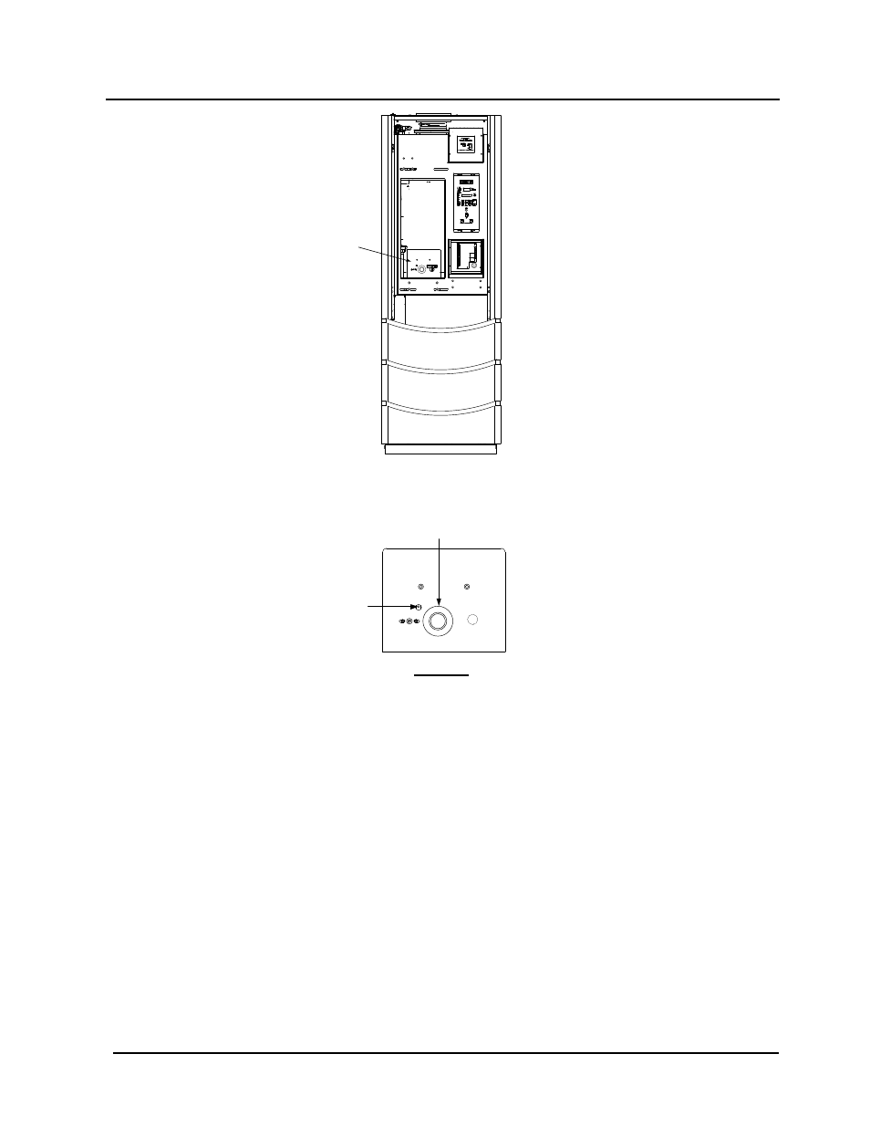
Page 76: Figure 6-2: temperature limit switch setting
Chapter 6
Benchmark 2.0LN Low NOx Boiler
GF-123
Safety Device Tests
Installation, Operation and Maintenance Manual
OMM-0046_0E
Page 76 of 170
AERCO International Inc.● 100 Oritani Dr. ● Blauvelt, NY 10913. ● Ph: 800-526-0288 PR1 08/20/12
FRONT VIEW
ADJUSTABLE
TEMPERATURE
LIMIT SWITCH
RESET BUTTON
FOR MANUAL
TEMPERATURE
LIMIT SWITCH
SEE
DETAIL “A”
DETAIL “A”
Figure 6-2: Temperature Limit Switch Setting
6. Once the adjustable over-temperature switch setting is approximately at, or just below, the
actual outlet water temperature, the unit should shut down. The FAULT indicator should
start flashing and a HIGH WATER TEMP SWITCH OPEN fault message should be
displayed. It should not be possible to restart the unit.
7. Reset the adjustable over-temperature switch to its original setting.
8. The unit should start once the adjustable temperature limit switch setting is above the actual
outlet water temperature.
6.6 INTERLOCK TESTS
The unit is equipped with two interlock circuits called the Remote Interlock and Delayed
Interlock. Terminal connections for these circuits are located in the I/O Box (Figure 2-9) and are
labeled REMOTE INTL’K IN and DELAYED INTL’K IN. These circuits can shut down the unit in
the event that an interlock is opened. These interlocks are shipped from the factory jumpered
(closed). However, each of these interlocks may be utilized in the field as a remote stop and
start, an emergency cut-off, or to prove that a device such as a pump, gas booster, or louver is
operational.