Benchmark 2.0ln low nox boiler, Gf-123 – AERCO BMK 2.0 LN Natural Gas (SN G-11-1861 and above) User Manual
Page 54
Chapter 4
Benchmark 2.0LN Low NOx Boiler
GF-123
Initial Start-Up
Installation, Operation and Maintenance Manual
OMM-0046_0E
Page 54 of 170
AERCO International Inc.● 100 Oritani Dr. ● Blauvelt, NY 10913. ● Ph: 800-526-0288 PR1 08/20/12
12. With the valve position at 100%, insert the combustion analyzer probe into the flue probe
opening and allow enough time for the combustion analyzer reading to stabilize.
13. Compare the measured oxygen level to the oxygen range for the inlet air temperature
shown in Table 4-1. Also, ensure that the carbon monoxide (CO) and nitrogen oxide (NOx)
readings do not exceed the values shown.
Table 4-1: Combustion Oxygen Levels for a
100%
Air/Fuel Valve Position
Inlet Air
Temp
Oxygen %
± 0.2
Carbon
Monoxide
NOx
>100°F
4.8 %
<100 ppm
<30 ppm
90°F
5.0 %
<100 ppm
<30 ppm
80°F
5.2 %
<100 ppm
<30 ppm
<70°F
5.3 %
<100 ppm
<30 ppm
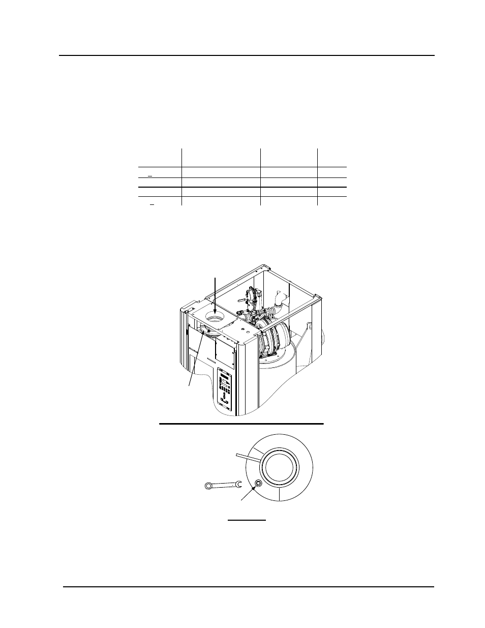
14. If necessary, adjust the iris air damper shown in Figure 4-5 until the oxygen level is within
the range specified in Table 4-1.
15. Once the oxygen level is within the specified range at 100%, lower the valve position to
80%.
AIR
INLET
IRIS AIR
DAMPER
(SEE VIEW
“A”)
USE 1/2"
WRENCH TO
INCREASE
(CW) OR
DECREASE
(CCW) INLET
AIR
IRIS
ADJUSTMENT
VIEW A - A
Figure 4-5: Iris Air Damper Location/Adjustment