1 exhaust manifold condensate drain, Gf-123, Benchmark 2.0ln low nox boiler – AERCO BMK 2.0 LN Natural Gas (SN G-11-1861 and above) User Manual
Page 19
GF-123
Benchmark 2.0LN Low NOx Boiler
Chapter 2
OMM-0046_0E
Installation, Operation and Maintenance Manual
Installation
PR1 08/20/12
AERCO International Inc.● 100 Oritani Dr. ● Blauvelt, NY 10913. ● Ph: 800-526-0288
Page 19 of 170
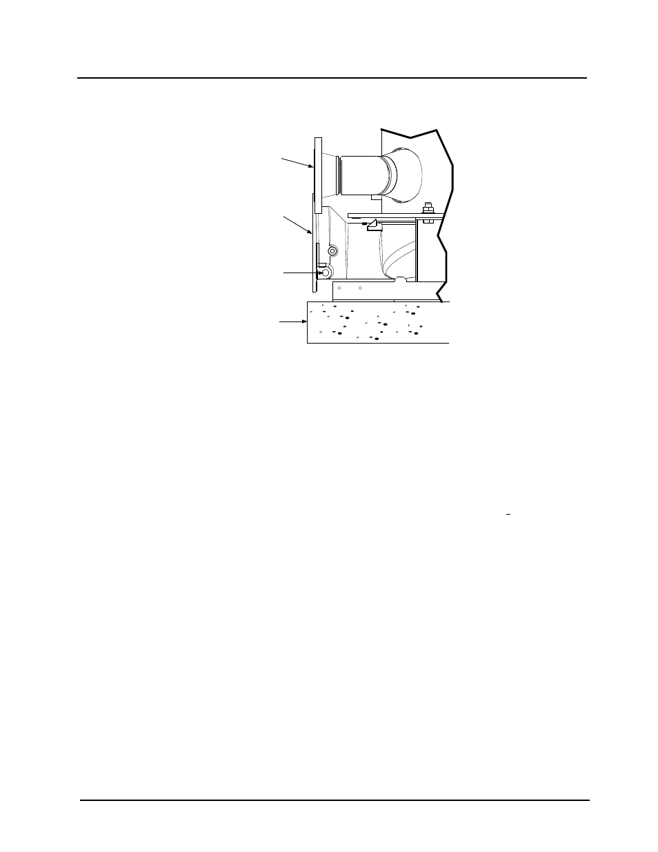
The procedure to install and connect the condensate drain is provided in paragraph 2.6.1.
EXHAUST
MANIFOLD
1/2” NPT
CONDENSATE
DRAIN
CONNECTION
HOUSE-
KEEPING
PAD
BOILER
RETURN
Figure 2-4: Condensate Drain Connection Location
2.6.1 Exhaust Manifold Condensate Drain
NOTE
There are two slightly different types of condensate traps that may be used
in your configuration; an older style without built-in adapter, and a newer
style with a built-in adapter (see Figure 2-5). Installation is the same (1/4”
threads are inside built-in adapter on newer style).
A condensate drain trap (part no. 24060) is shipped loose and must be installed at the rear of
the unit. The trap inlet and outlet contain tapped 3/4” NPT ports. The actual installation details
for the condensate trap will depend on the available clearances, housekeeping pad
height/dimensions and other prevailing conditions at the site. However, the following guidelines
must be observed to ensure proper condensate trap operation:
• The condensate trap inlet (Figure 2-5) must be level with, or lower than the exhaust
manifold drain port.
• The condensate trap must be supported to ensure that its base is level (horizontal).
• The trap must be removable for routine maintenance. AERCO recommends that a
union be utilized between the exhaust manifold condensate drain port and the trap
inlet port.
While observing the above guidelines, connect the condensate trap inlet to the exhaust manifold
drain connection using the appropriate piping components (nipples, reducers, elbows, etc.) for
the boiler installation site. Connect as follows:
1. At the condensate trap outlet, install a 3/4” NPT nipple.
2. Connect a length of 1” I.D polypropylene hose to the trap outlet and secure with a hose
clamp.
3. Route the hose on the trap outlet to a nearby floor drain.