1 combination control system field wiring, 2 combination control system setup and startup, Gf-123 – AERCO BMK 2.0 LN Natural Gas (SN G-11-1861 and above) User Manual
Page 71: Benchmark 2.0ln low nox boiler
GF-123
Benchmark 2.0LN Low NOx Boiler
Chapter 5
OMM-0046_0E
I
nstallation, Operation and Maintenance Manual
Mode of Operation
PR1 08/20/12
AERCO International Inc.● 100 Oritani Dr. ● Blauvelt, NY 10913. ● Ph: 800-526-0288
Page 71 of 170
to the BMS mode. For more information concerning the operation of the Combination Control
Panel see the AERCO CCP-1 literature (BMS 168 applications) and TAG-0050 (ACS).
5.7.1 Combination Control System Field Wiring
Wiring for this system is between the BMS Model 168 panel, the CCP and the B.M.S. (PWM) IN
terminals in the I/O Box. For ACS applications, the wiring is between the ACS panel, the ACS
Replay Panel (optional, depending on application), and the RS485 Comm terminals in the I/O
box. Wire the units using a shielded twisted pair of 18 to 22 AWG wire. When wiring multiple
units, each unit’s wiring must conform to the above. For a complete CCP system-wiring diagram
see the AERCO CCP-1 literature (BMS 168 applications) and TAG-0050 (ACS).
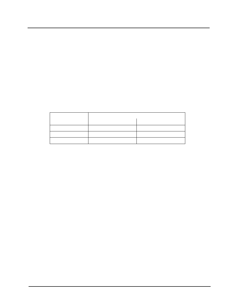
5.7.2 Combination Control System Setup and Startup
Setup for the Combination Mode requires entries to be made in the Configuration Menu for
boiler mode, remote signal type and setpoint. The setpoint is adjustable from 40°F to 240°F.
Enter the following settings in the Configuration Menu:
MENU OPTION
SETTINGS
BMS 168 Applications
ACS Applications
Boiler Mode
Combination
Combination
Remote Signal
BMS (PWM Input)
Network (RS485)
Internal Setpt
40°F to 240°F
40°F to 240°F
Refer to paragraph 3.3 for instructions on changing menu options.
While it is possible to change other temperature-related functions for combination mode, thes
functions are preset to their factory default values. These default settings work well in most
applications. It is suggested that AERCO be contacted prior to changing settings other than the
unit’s setpoint. For a complete listing of temperature related function defaults, see Appendix E.
To set the unit to the manual mode, press the AUTO/MAN switch. The MANUAL LED will light.
To set the unit back to the auto mode, press the AUTO/MAN switch. The MANUAL LED will go
off and the REMOTE LED will light.
When the boiler is switched to BMS mode, the AERCO BMS/ACS controls the valve position.
There are no setup requirements to the boiler(s) in this mode.