3 setting the bl-u1 dip switches, Power supply bl-u1, Caution – KEYENCE BL-180 User Manual
Page 90
Power Supply BL-U1
84
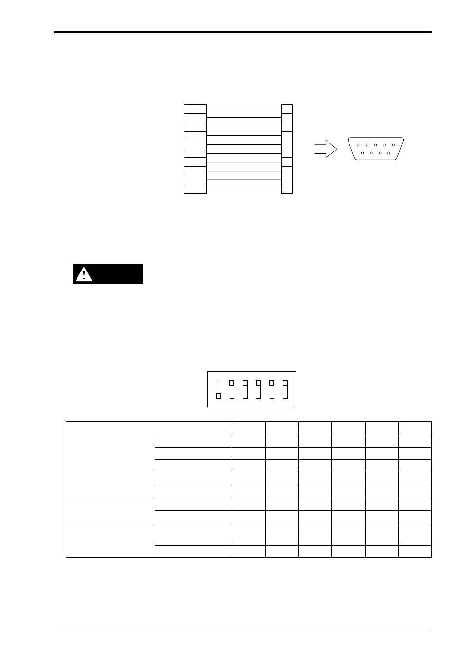
Prepare the BL series for connection to the BL-U1 by soldering a D-sub 9-pin con-
nector to the BL series cable. Then connect the cable to READER port of the BL-
U1.
Prepare the D-sub 9-pin connector and its connector case separately.
Take special care when soldering pin 5 (GND) and pin 9 (+5VDC). A wrong con-
nection will damage the unit.
Do not use a power cable over 2 meters long. A long power cable can cause a
drop in voltage, preventing the BL series from starting up properly.
1.3
Setting the BL-U1 DIP switches
According to the selected interface and timing input, change the DIP switch set-
tings.
Shield
Yellow
Blown
Purple
White
Black
Gray
BL series
1
2
-
3
5
6
4
7
Connector case
TIM
RD
SD
OK
GND
NG
RS
Pink
Blue
Red
8
9
CS
+5VDC
D-sub 9-pin (female)
#4-40 screw
READER port
BL-U1
Use a metallic connector case for the D-sub 9-pin connector and connect the
shielded line to the connector case. This allows connection to the earth ground of
the AC power cable.
CAUTION
OFF
ON
1
2
3
4
5
6
The switch settings at left are the
factory default settings.
DIP switch setting
1
2
3
4
5
6
Interface select
RS-232C
ON
OFF
OFF
RS-422A
OFF
ON
OFF
RS-485 multidrop
OFF
OFF
ON
RS-422A terminator
(terminal resistance 100
Ω
)
OFF
OFF
ON
ON
RS-485 terminator
(terminal resistance 100
Ω
)
OFF
OFF
ON
ON
READER port CS control
method select
Reflect ON/OFF of CS
at RS-232C port
OFF
Always ON
ON