1 bl-180 connections, 1 wire colors and signal types, 2 power supply wiring – KEYENCE BL-180 User Manual
Page 10: 3 wiring i/o
1.1 BL-180 Connections
2
1.1
BL-180 Connections
1.1.1
Wire colors and signal types
The following wires extend from the BL-180. Solder the required wires to a con-
nector to connect the BL-180 to a computer/controller.
1.1.2
Power supply wiring
• Be sure to match the polarities of the power supply when soldering the con-
nections. Reversing the polarities will damage the unit.
• Make sure that the power supply provides a stable 5 VDC ± 5%. If the power
supply does not function in the above range, it can damage the unit.
• Do not use a power cable longer that 2 meters. A long power cable can cause
a voltage drop, preventing the BL-180 from starting properly.
• If the power supply is UL rated, it must provide Class 2 output.
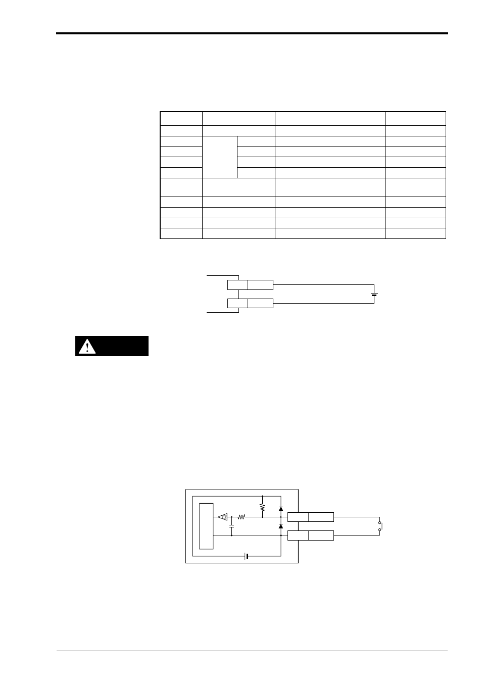
1.1.3
Wiring I/O
Trigger (TIM) input
The trigger input is used to signal the BL-180 to start reading (Start laser emis-
sion).
The trigger input is a non-voltage input (TTL input is also available).
Wire Color
Symbol
Description
Signal Direction
Shield
Shield
Connect to ground (SG)
——
Purple
RS-
232C
SD (TXD) Send data
Output
Brown
RD (RXD) Receive data
Input
Pink
RS (RTS) Request to send (always on)
Output
Blue
CS (CTS) Request to receive
Input
Black
GND (SG)
Ground (common ground for
respective signals)
——
Yellow
TIM
Trigger input
Input
White
OK
OK output
Output
Gray
NG
NG output
Output
Red
+ 5V
+ 5V power supply input
Input
5VDC
BL-180
+5V
Red
GND
Black
+
CAUTION
GND
TIM
Yellow
Black
5VDC
10K
Ω
4.7
K
Ω
BL-180
Internal circuit
With or
without relay