4 rs-232c connections, 1 bl-180 connections – KEYENCE BL-180 User Manual
Page 11
1.1 BL-180 Connections
3
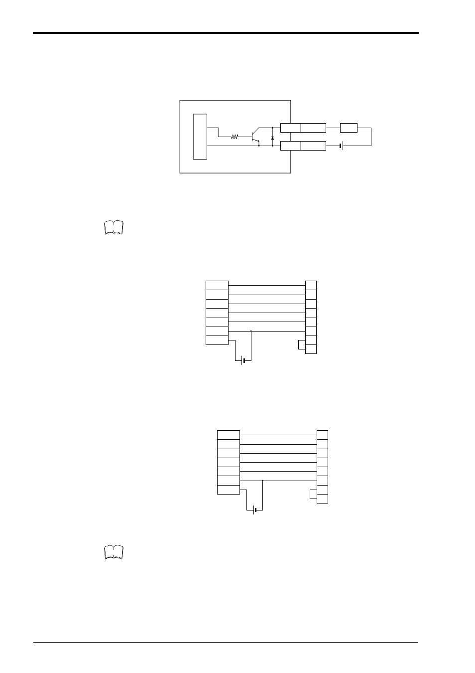
OK/NG output
This output signals whether the readout data is the same as the preset data.
When no preset data has been registered, the signal indicates bar code read sta-
tus. It is an NPN open-collector output.
1.1.4
RS-232C Connections
This BL-180 setup software applies to port 1 and port 2 only.
Communication cannot be performed with another port.
When using a D-sub 9-pin connector:
Use a metallic connector housing for the D-sub 9-pin connector. Connect the
shielded cable with the connector housing.
When using a D-sub 25-pin connector:
Be sure the BL-180’s shielded cable is properly connected. Refer to “1.1.3 Con-
necting shielded cables” in the User’s Manual.
GND
OK/NG
Write/Gray
Black
Load
BL-180
1k
Ω
*Rated load: 24 VDC
(100 mA) max.
+
Internal circuit
Note
Purple
Shield
Blown
Blue
Pink
Black
Red
5VDC
BL-180
SD
RD
CS
RS
GND
+5V
PC
2
–
3
7
5
4
8
6
RD
Shield
Connector case
SD
RS
CS
SG
DR
ER
D-sub 9-pin (male)
# 4-40 screw
+
Purple
Shield
Blown
Blue
Pink
Black
Red
5VDC
BL-180
RD
SD
CS
RS
GND
+5V
PC
2
1
3
4
7
6
5
20
SD
Shield
FG
RD
RS
CS
SG
DR
ER
D-sub 25-pin (male)
M 2..6 screw
+
Note